
Anti-aliasing low-pass blur filter for reducing artifacts in imaging apparatus

a low-pass blur filter and filter technology, applied in the field of low-pass optical filters, can solve the problems of aliasing or undersampling artifacts, spurious signals, and unfavorable image quality improvement, and achieve the effects of reducing the cost of filtering and cementing, and reducing the number of components

Inactive Publication Date: 2005-08-30
INTELLECTUAL VENTURES FUND 83 LLC
View PDF22 Cites 13 Cited by
  • Summary
  • Abstract
  • Description
  • Claims
  • Application Information

AI Technical Summary

Benefits of technology

[0024]It is therefore an object of the present invention to provide a physically thin blur filter that is inexpensive and relatively simple to manufacture, yet which produces a tightly controlled blur pattern that is not dependent upon polarization techniques.
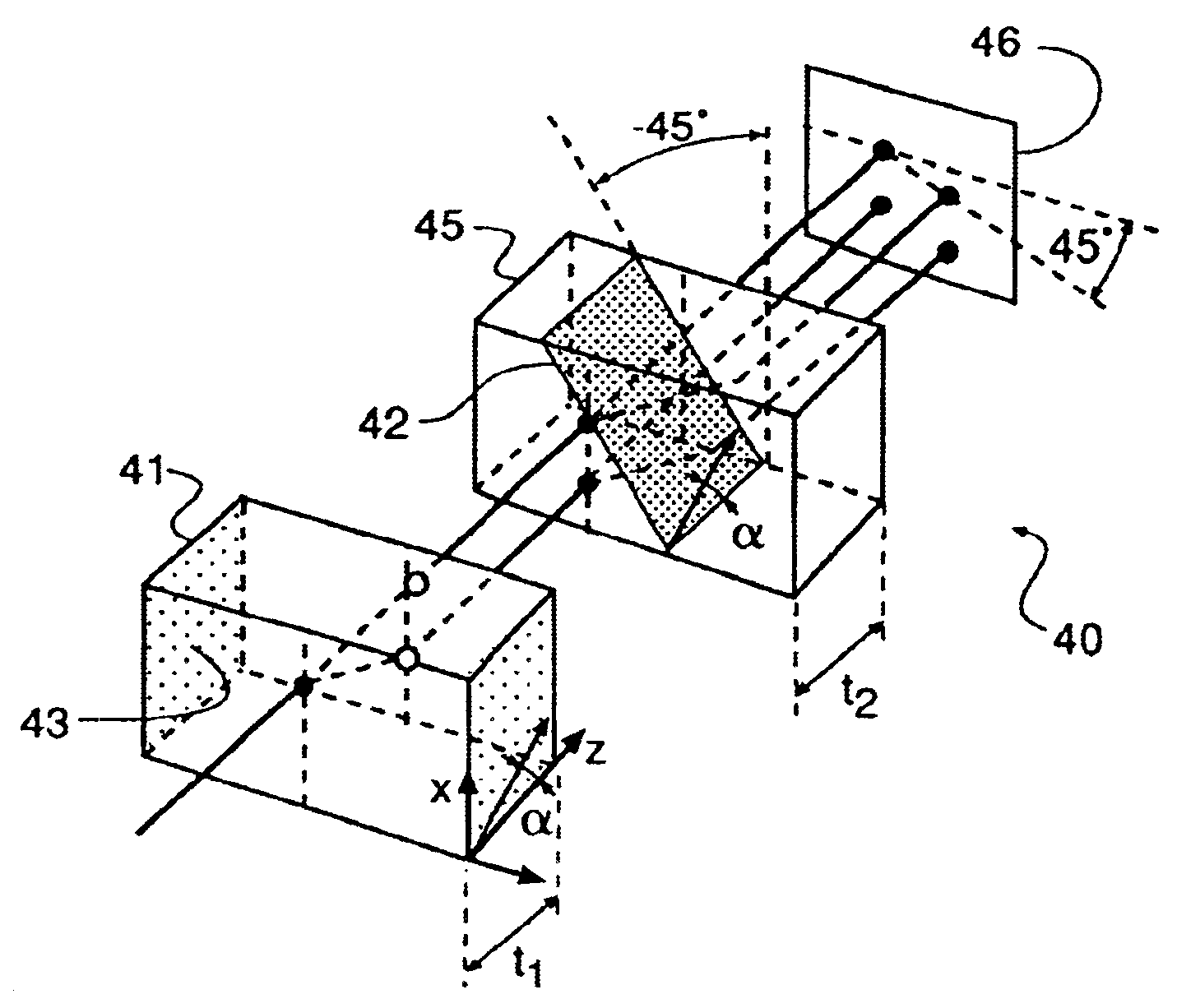
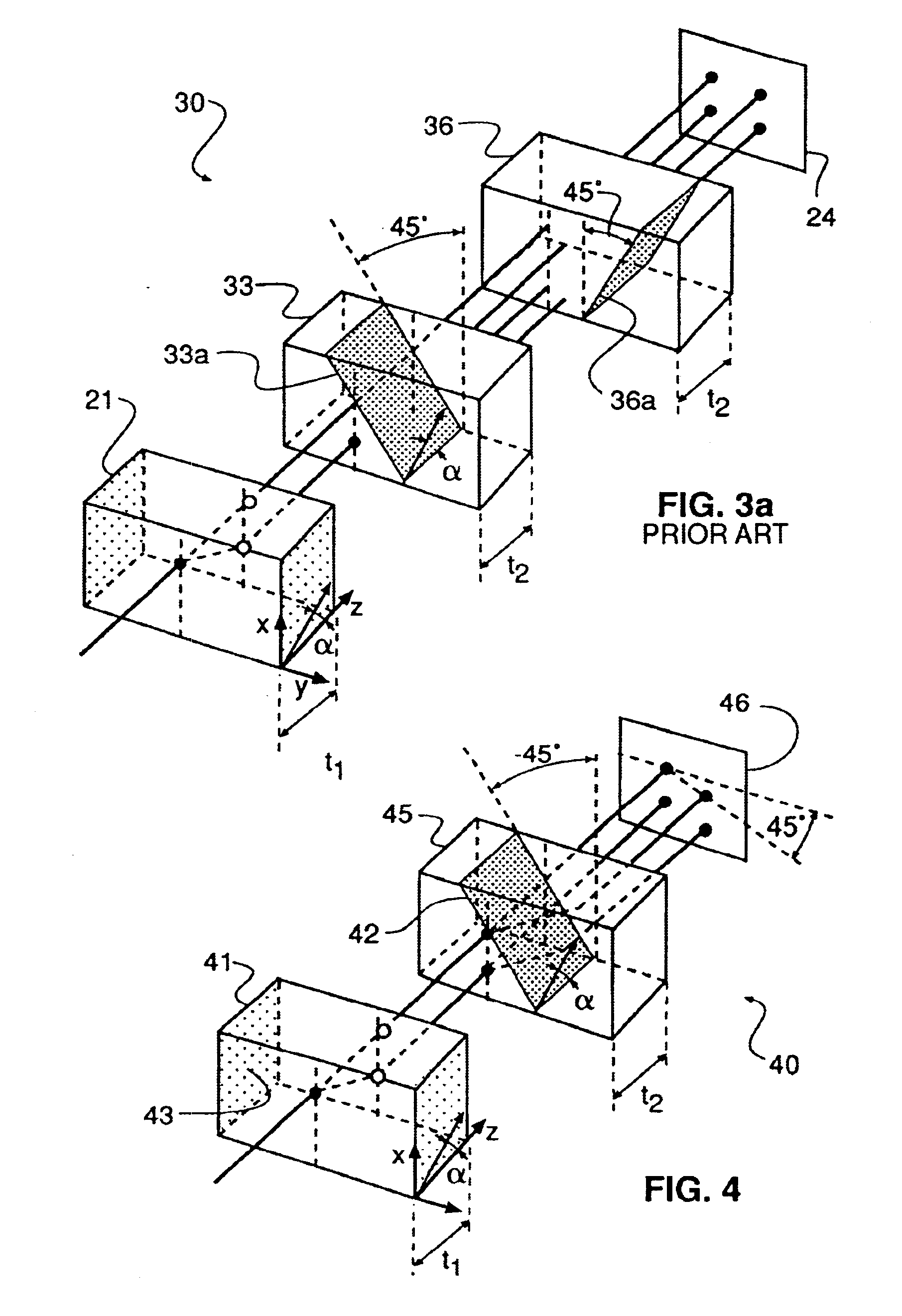
[0027]Another aspect of the current invention is a rhomboidal four spot blur filter which uses a total of only two plates with their optical axis at 45° to each other. The filter is rotated about the camera axis to efficiently reduce aliasing artifacts. Reducing the number of components in the filter reduces the cost of the filter and the cost of cementing since only one cementing operation is needed per filter instead of two.

Problems solved by technology

In such an imaging system, it is well-known that components in the object which contain fine details create frequencies too high to be analyzed within the sampling interval of the sensor and contribute to the amplitudes of lower frequency components, thereby produce imaging errors commonly referred to as aliasing or undersampling artifacts.
In particular, if the spatial detail being imaged contains a high frequency component of a periodicity smaller than the pitch of the photosensitive picture elements of the solid state image sensor, the subsequent detection of this high frequency component tends to result in a spurious signal due to aliasing.
Thus, prior art design of electronic imaging systems involves a trade-off between image sharpness and the susceptibility of the imaging system to aliasing distortions or undersampling artifacts.
The filters discussed above, however, suffer from the drawback that the thickness required to achieve the desired blur requires a lens with a long, back focal distance in order to make room for the blur filter in the optical path.
Space limitations often do not allow such an optical structure, and lens design becomes unduly complicated.
Also, when a digital camera which was originally designed as film camera is modified for use with a CCD detector, in addition to the mechanical problems associated with accommodating a thick blur filter, a lens designed for film may not perform as well with a thick filter, which may introduce aberrations.
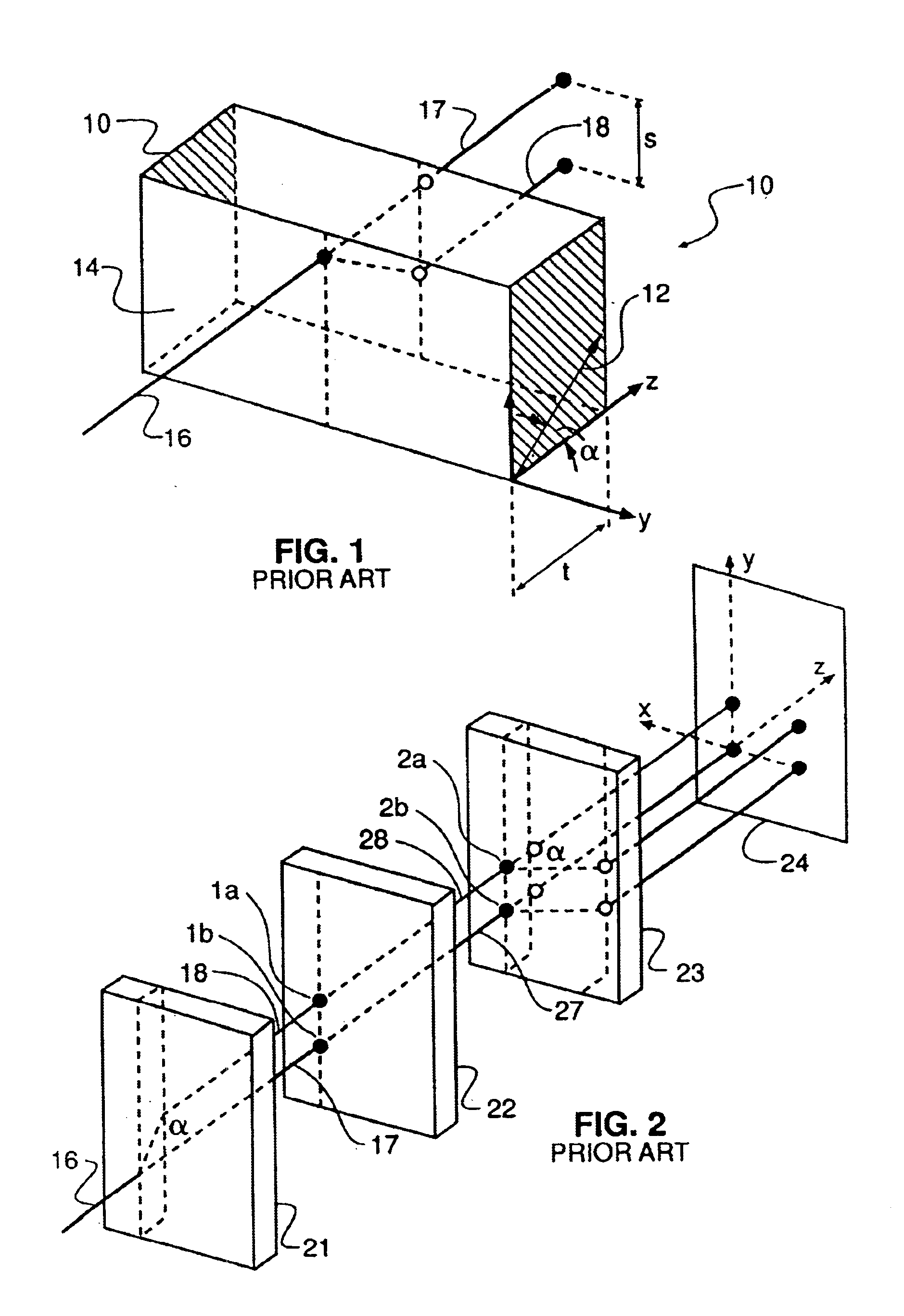
Another problem with current art four spot filters is that they are commonly made of three pieces, either two double refractors and a retarder as in the Sato, U.S. Pat. No. 4,626,897; or as in FIG. 3a, which uses three double refractor plates without a retarder.
In most modern CCD images, a color filter array used is commonly a two-dimensional array of color filters as in Bayer U.S. Pat. No. 3,971,065, and a blur filter is required to split the imaging spot into four or more spots arranged in a two-dimensional pattern, so the Watanabe design would not be satisfactory.
This type of filter, however, suffers from the drawback that, instead of producing a tightly controlled pattern over a few photosensitive elements, it spreads light over many interference fringes (orders) theoretically out to infinity.
In addition, it is difficult to control the energy distribution in the fringes in order to obtain an acceptable blur function covering a designated number of pixels.
This filter produces the desired spots at the CCD plane when the lens is at focus, however, as the lens is slightly defocused, the spots tend to blend and the anti-aliasing efficiency is diminished.
Since the filter is focal length dependent, it will not work with a zoom lens.
Although this is a very good filter if there is ready access to the pupil, it too is located at the aperture and may confuse an auto focus system, if there is one, and will not work with a zoom system.
Calcite can also be used, however calcite is very hard to grind and polish.

Method used


Image

  • Anti-aliasing low-pass blur filter for reducing artifacts in imaging apparatus
  • Anti-aliasing low-pass blur filter for reducing artifacts in imaging apparatus
  • Anti-aliasing low-pass blur filter for reducing artifacts in imaging apparatus

Examples


Embodiment Construction

[0034]The present description is directed in particular to elements forming part of an apparatus in accordance with the present invention. It is to be understood that elements not specifically shown or described may take various forms well known to those skilled in the art. For instance, geometrical relationships of the optical components are not shown or described in detail, except where necessary to describe the invention. Moreover, relative sizings of components shown in the figures are not meant to be taken to scale, since the necessary geometrical relationships and sizings can be readily discerned by one of ordinary skill in this art.

[0035]Referring to FIG. 4, the preferred embodiment of a blur filter, referred to in general by numeral 40, according to the present invention is shown. A first double refractor 41 produces polarized light at each of the two spots. A second double refractor 45 has a plane 42, that is tilted at 45° to a first plane 43. The polarized light beam creat...


PUM


Abstract

An imaging apparatus (50) for generating an image signal from incident light with higher spatial frequencies of the incident light limited to reduce undersampling artifacts. Apparatus (50) includes a detector plane (62) for generating the image signal from an array of photosites, (63) and an optical section having a relatively thin lithium niobate rhomboidal filter (51) interposed in the path of the incident light so as to produce a blurred image on the photosites. A filter configuration is disclosed which produces four spots (58) at the imaging sensors (62) positioned at the corners of a rhombus.

Description

BACKGROUND OF THE INVENTION[0001]1. Technical Field[0002]The present invention pertains to a low-pass optical filter used in an electronic imaging system to reduce aliasing or undersampling artifacts.[0003]2. Background Art[0004]An electronic imaging system typically produces a signal output corresponding to a viewed object by spatially sampling an image of the object in a regular pattern with an array of photosensitive elements, such as, for example, a charge-coupled device (CCD) solid-state image sensor. In such an imaging system, it is well-known that components in the object which contain fine details create frequencies too high to be analyzed within the sampling interval of the sensor and contribute to the amplitudes of lower frequency components, thereby produce imaging errors commonly referred to as aliasing or undersampling artifacts. In particular, if the spatial detail being imaged contains a high frequency component of a periodicity smaller than the pitch of the photosens...

Claims


Application Information

Patent Timeline
Patent Type & Authority Patents(United States)
IPC IPC(8): G02B5/30G02B27/46H04N9/077H04N1/04H04N1/195G02B5/20H04N25/00H04N9/01H04N23/75
CPCG02B5/3083G02B27/46H04N9/077H04N1/195H04N9/01
Inventor KESSLER, DAVIDNUTT, ALAN C. G.PALUM, RUSSELL J.
Owner INTELLECTUAL VENTURES FUND 83 LLC
Learn More