
Thermal imaging paper laminate

a technology of thermal imaging paper and laminate, which is applied in the field of thermal imaging paper, can solve problems such as unfavorable interference with wireless communication

Inactive Publication Date: 2005-08-30
APPVION LLC
View PDF13 Cites 37 Cited by
  • Summary
  • Abstract
  • Description
  • Claims
  • Application Information

AI Technical Summary

Benefits of technology

"The present invention provides a thermal imaging laminate structure with a wireless memory device for thermal imaging applications. The laminate structure includes a thermal imaging paper substrate, a foam layer, a wireless memory device, and an adhesive layer. The wireless memory device is positioned between the thermal imaging paper substrate and the adhesive layer. The laminate structure can be used in a thermal printing device and provides security features such as a wireless device and a thermal printed paper product with the wireless device incorporated. The technical effects of the invention include improved thermal imaging capabilities and enhanced security features."

Problems solved by technology

If the antenna in an RF tag is too close to the device to which it is installed, unfavorable interference with wireless communications may be experienced, especially when the underlying container is made of metal.

Method used


Image

  • Thermal imaging paper laminate
  • Thermal imaging paper laminate
  • Thermal imaging paper laminate

Examples


second embodiment

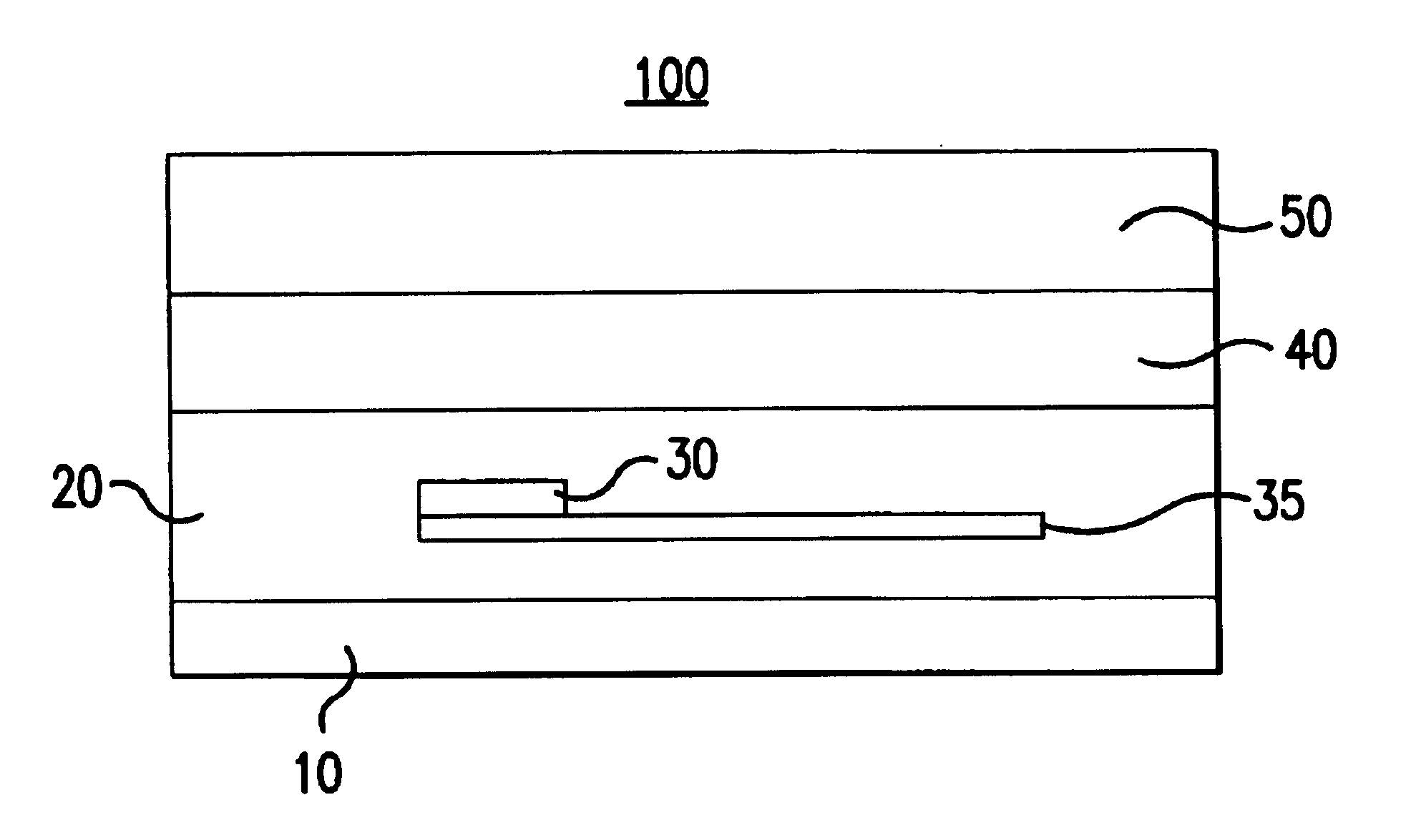
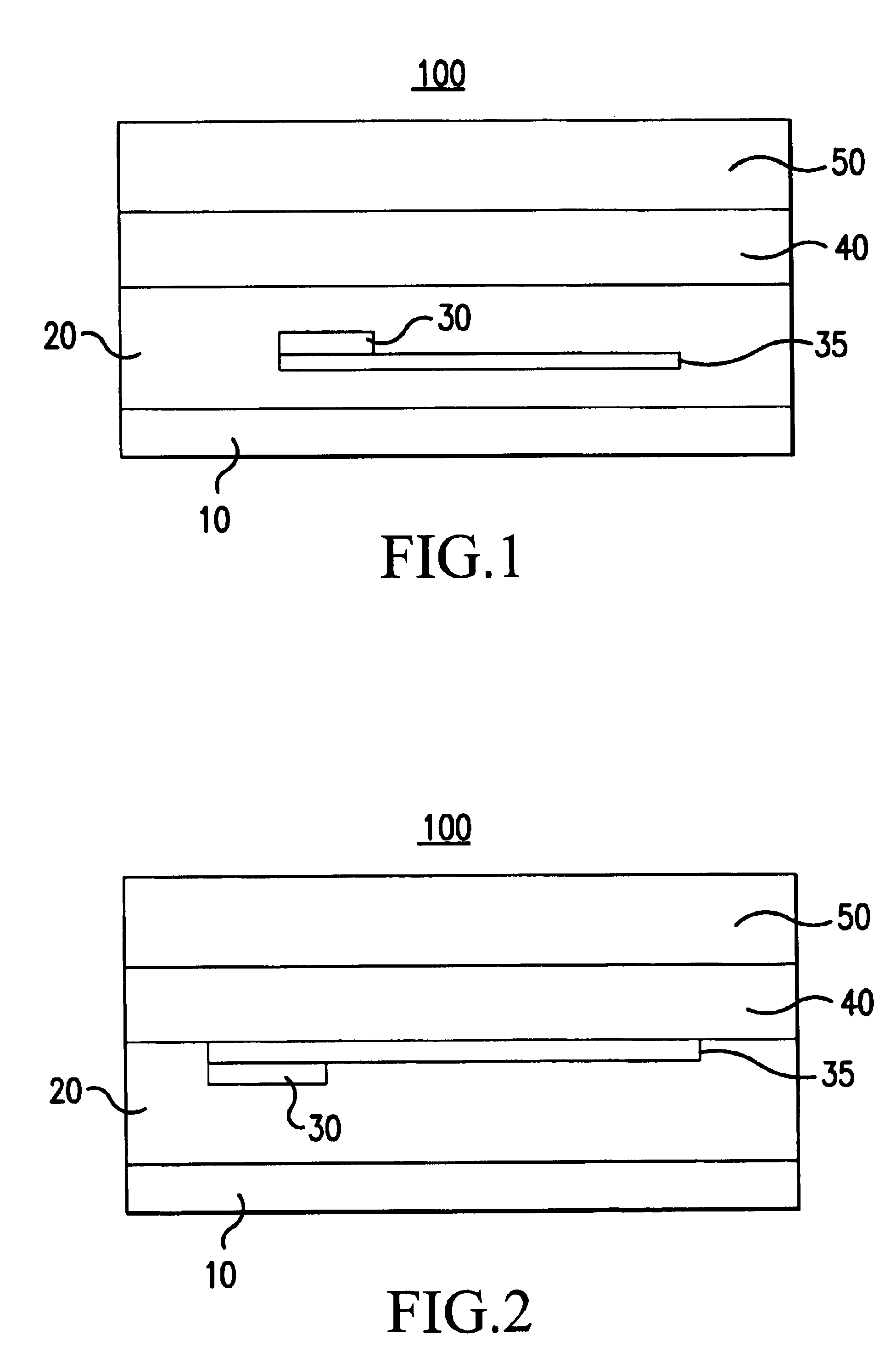
[0043]FIG. 2 is a sectional view of a thermal imaging laminate structure according to the present invention. The cushioning layer 20 is formed so as to surround the wireless memory device 30, 35 in this embodiment. However, the wireless memory device 30, 35 is actually positioned adjacent to the thermal imaging heat sensitive layer 40, and with the antenna 35 positioned on an adhesive side of the inlay 30, 32, e.g., opposite to that shown in FIG. 1. Alternatively, the wireless memory device 30, 35 can be provided in the form of a substrate 32 whereby the IC substrate 32 extends the entire width of the section shown in FIG. 2. In this arrangement (not shown in FIG. 2), since the side of the IC substrate 32 closest to the thermal imaging substrate 40 would already present a smooth printing surface, e.g., no bumps, only the antenna 35 would actually be surrounded by the cushioning layer 20.

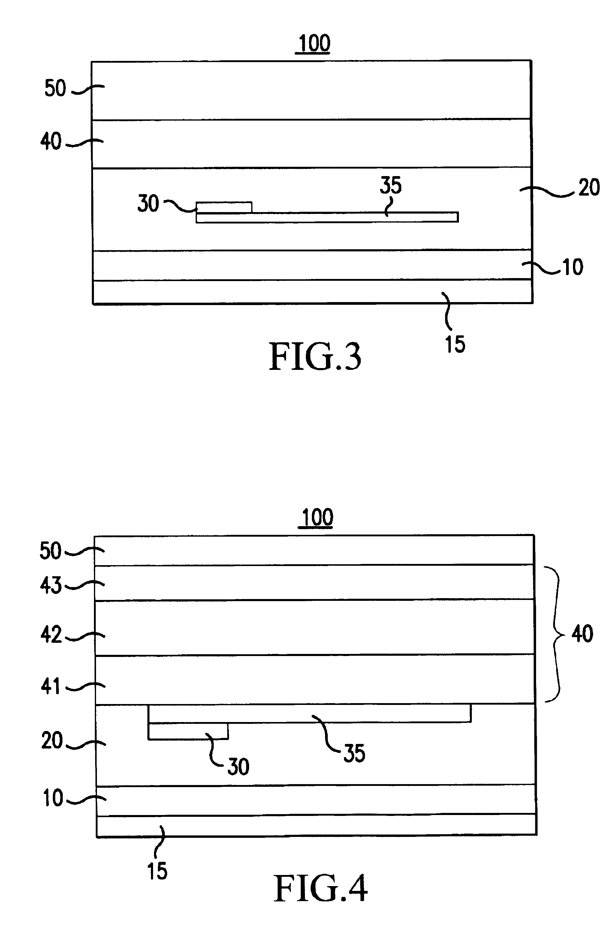
[0044]FIG. 3 is a sectional view of a thermal imaging laminate structure according to a third emb...

fifth embodiment

[0047]FIG. 5 is a sectional view of a thermal imaging laminate structure according to the present invention. In FIG. 5, the wireless memory device is not embedded in a cushioning layer 20. Instead, a pressure sensitive adhesive layer 10 and an IC substrate 32 having an integral antenna (see FIG. 6) is applied over the cushioning layer 20. In the embodiment shown, the wireless memory device 30, 35 is typically applied prior to the application of the adhesive layer 10.

[0048]A suitable pressure sensitive adhesive for the adhesive layer 10 is any acrylic pressure sensitive adhesive commonly used with a release liner 15. One of skill in the art will also appreciate that the pressure sensitive adhesive layer 20 can easily be replaced by other adhesives commonly available in the related art of adhesives, including but not limited to encapsulated adhesives that do not necessarily require a release liner 15 layer to protect the adhesive layer 10 during ordinary handling prior to installation...


PUM

PropertyMeasurementUnit
heat sensitiveaaaaaaaaaa
electronic structureaaaaaaaaaa
pressureaaaaaaaaaa

Abstract

A thermal imaging paper having a laminate structure is disclosed. The laminate structure includes a thermal imaging heat sensitive substrate, an adhesive layer, and a polyfoam layer. In addition, a security feature such as an antenna and integrated circuit are provided in a position interposed between said adhesive layer and said thermal imaging heat sensitive substrate. The thermal imaging paper provides the combination of an effective thermal imaging paper product incorporating the benefits of a security feature such as a wireless memory device.

Description

BACKGROUND OF THE INVENTION[0001]1. Field of the Invention[0002]The present invention relates to a thermal imaging paper and a method of making a thermal imaging paper. In particular, the present invention relates to an thermal imaging laminate structure that includes a thermal imaging layer, an integrated circuit and antenna device, and a cushioning layer.[0003]2. Description of the Background Art[0004]Memory tags or labels for storing and retrieving data in the background art often employ a laminated circuit substrate positioned between a face sheet and a release liner. The memory devices for storing and retrieving data are well known in the related art, and include radio frequency (“RF”) tags that are readily available from a number of commercial manufacturers, including Texas Instruments and Phillips.[0005]The face sheet provides a protective layer over one surface of the circuit substrate, thereby protecting the antenna and the electronic structure. A pressure sensitive adhesiv...

Claims


Application Information

Patent Timeline
Patent Type & Authority Patents(United States)
IPC IPC(8): G08B13/24G06K19/07G01D15/00G06K19/077G08B1/00G08B13/22G09F3/00G09F3/02
CPCG06K19/07745G06K19/0776G08B13/2434Y10T156/10H01L2924/0002H01L2924/00
Inventor REDLIN, GREGORY GEORGE
Owner APPVION LLC
Learn More