
Blood collection agency

Inactive Publication Date: 2005-08-30
BECTON DICKINSON & CO
View PDF27 Cites 42 Cited by
  • Summary
  • Abstract
  • Description
  • Claims
  • Application Information

AI Technical Summary

Benefits of technology

[0006]For example, existing blood collection systems typically employ some form of durable, reusable holder on which detachable and disposable needles and fluid collection tubes may be mounted. A blood collection system of this nature can be assembled prior to use and then disassembled after usage. Thus, these blood collection systems allow repeated use of the relatively expensive holder upon replacement of the relatively inexpensive needle and / or fluid collection tube. In addition to reducing the cost of collecting blood specimens, these blood collection systems also help minimize the production of hazardous medical waste. A blood collection set or intravenous (IV) infusion set typically includes a needle cannula having a proximal end, a pointed distal end and a lumen extending therebetween. The proximal end of the needle cannula is securely mounted in a plastic hub with a central passage that communicates with the lumen through the needle cannula. A thin flexible thermoplastic tube is connected to the hub and communicates with the lumen of the needle cannula. The end of the plastic tube remote from the needle cannula may include a fixture for connecting the needle cannula to a blood collection tube or some other receptacle. The specific construction of the fixture will depend upon the characteristics of the receptacle to which the fixture will be connected.

Problems solved by technology

Thus, these blood collection systems allow repeated use of the relatively expensive holder upon replacement of the relatively inexpensive needle and / or fluid collection tube.
Needle assemblies including such tip guards, however, typically include extensive mechanics for positioning of the tip guard, resulting in complex arrangements which are costly to manufacture and assembly.
Also, operation of the tip guard can involve substantial manipulation by the user to extend the tip guard to a shielding position.

Method used


Image

  • Blood collection agency
  • Blood collection agency
  • Blood collection agency

Examples


Embodiment Construction

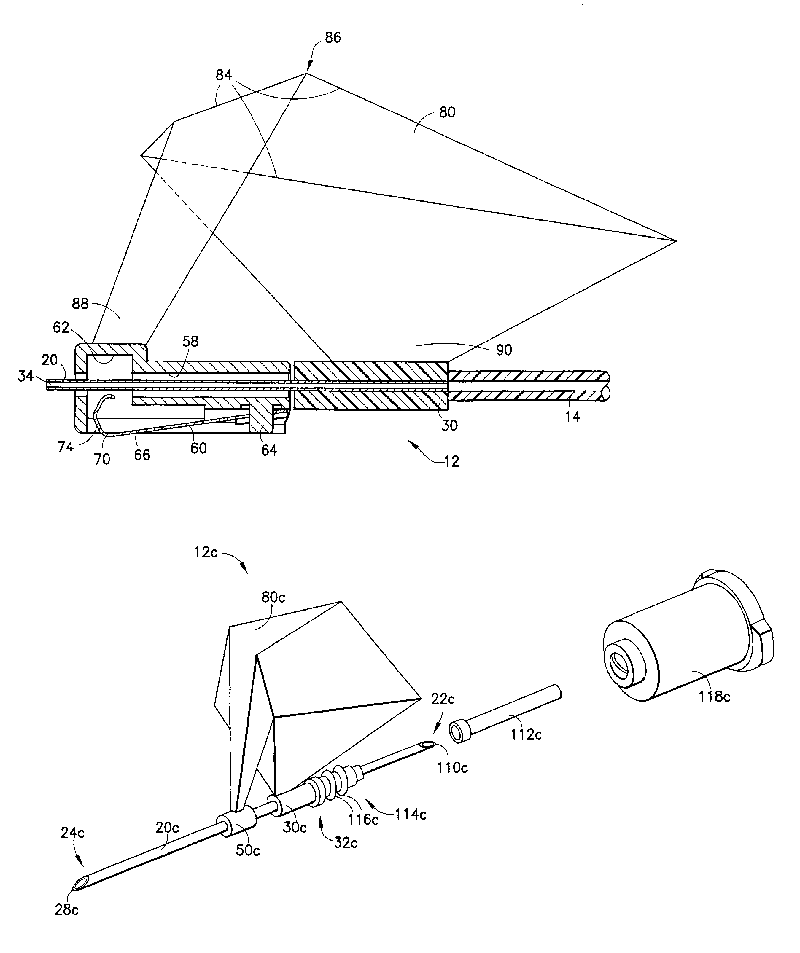
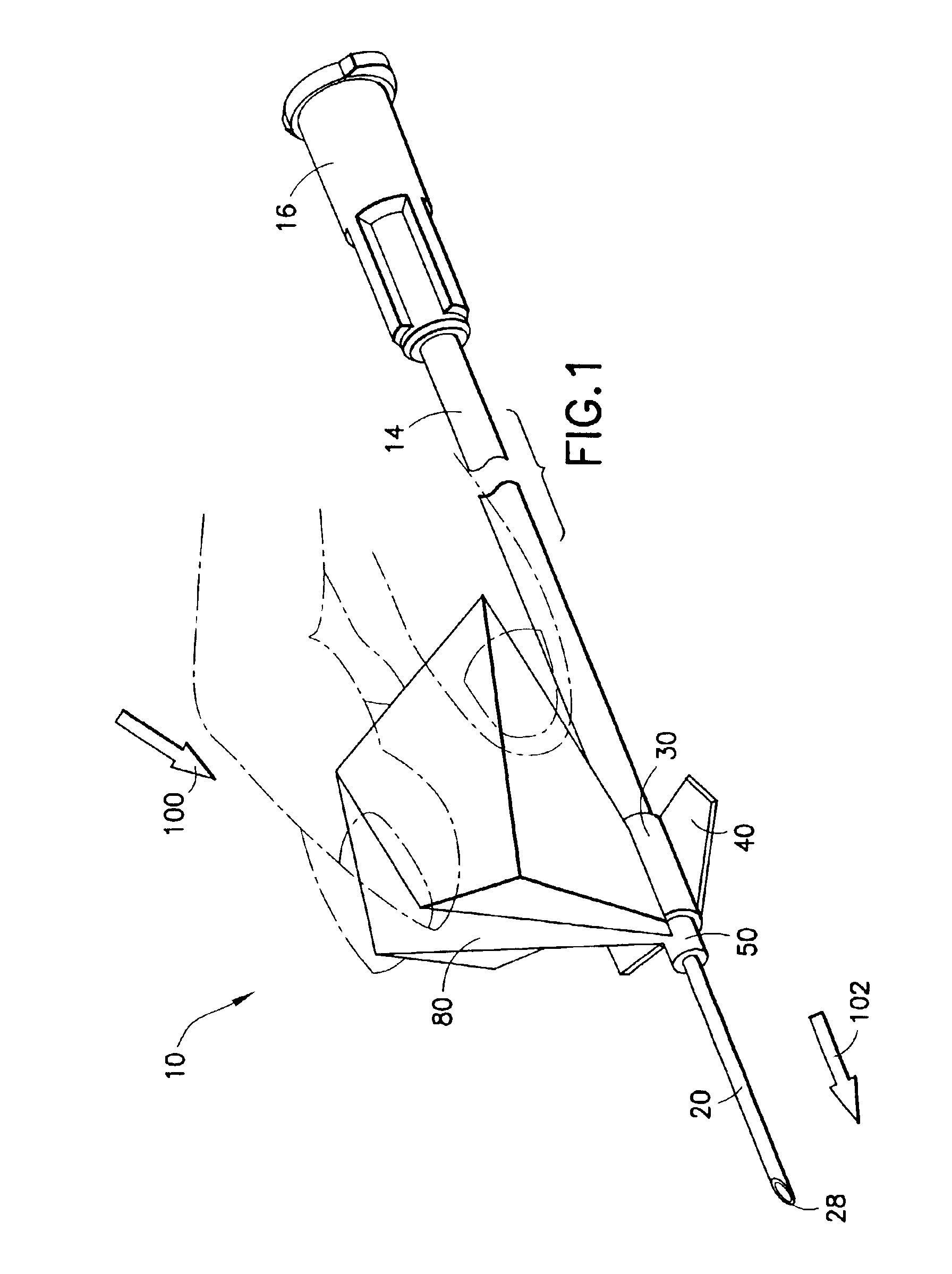
[0029]Referring to the drawings in which like reference characters refer to like parts throughout the several views thereof, FIGS. 1 and 5 illustrate a shieldable needle assembly, for use in connection with a blood collection set, in accordance with the present invention and the related features. The present invention is generally described in terms of a shieldable needle assembly, and encompasses a shieldable needle assembly as well as such a shieldable needle assembly for use with a medical device such as a blood collection set, a hypodermic syringe, a double ended needle assembly for blood collection, and the like. FIGS. 1 and 5 illustrate the shieldable needle assembly in the form of a blood collection set 10, including a shieldable needle device 12. While described in FIGS. 1-5 in terms of one embodiment of a blood collection set, the shieldable needle device of the present invention may incorporate other medical devices used in connection with a needle, such as a hypodermic sy...


PUM


Abstract

The present invention is directed to a low cost shieldable safety needle assembly. The assembly includes a needle cannula and a tip guard axially movable along the needle cannula through a drive mechanism. The drive mechanism may be interconnected between the tip guard and the needle cannula through a hub. The tip guard is axially movable along the needle cannula from a proximal position substantially adjacent a proximal end of the needle cannula at the hub, to a distal position in which the tip guard protectively surrounds the distal end of the needle cannula, thus effectively shielding the puncture tip of the needle. The drive mechanism is a unitary structure which is capable of maintaining a first self-supporting shape for maintaining the tip guard in the proximal position and is deflectable from the first self-supporting shape to a second extended shape in which the tip guard is moved to the distal position. The drive mechanism may be a rigid flexible planar sheet material which includes a plurality of folds for defining the self-supporting shape. The needle assembly may include structure for mating with a hypodermic syringe, a blood collection set, or other medical device.

Description

[0001]This application claims priority to U.S. Provisional Application Ser. No. 60 / 313,047 filed Aug. 17, 2001, entitled “Blood Collection Set”.BACKGROUND OF THE INVENTION[0002]1. Field of the Invention[0003]The present invention relates to safety needle assemblies for safe and convenient handling of needles. More particularly, the present invention relates to a low cost needle assembly having a safety shield.[0004]2. Description of Related Art[0005]Disposable medical devices having piercing elements are typically used for administering a medication or withdrawing a fluid, such as hypodermic syringes, blood collecting needles, fluid handling needles and assemblies thereof. Current medical practice requires that the fluid containers and needle assemblies used in such systems be inexpensive and readily disposable. Safe and convenient handling of disposable medical devices results in the disposal of the medical devices intact.[0006]For example, existing blood collection systems typical...

Claims


Application Information

Patent Timeline
IPC IPC(8): A61B5/145A61M5/32
CPCA61B5/14A61M5/3275A61M2005/325A61B5/15003A61B5/150389A61B5/150519A61B5/150564A61B5/150717A61B5/150732A61B5/15074A61B5/153A61B5/150587A61B5/150656A61M5/32
Inventor WILKINSON, BRADLEY M.SWENSON, KIRK D.
Owner BECTON DICKINSON & CO
Learn More