Method for protecting the diaphragm and extending the life of SiC and/or Si MEMS microvalves

a technology of micro-valves and diaphragms, which is applied in the direction of valve housings, valve operating devices/release devices, mechanical equipment, etc., can solve the problems of difficult shaping of the cavity or recess in any particular way, significant localized forces or stresses on the diaphragm, and inability to create contoured shapes, etc., to achieve the effect of reducing stress concentration

Inactive Publication Date: 2005-08-30
LOCKHEED MARTIN CORP
View PDF4 Cites 3 Cited by
  • Summary
  • Abstract
  • Description
  • Claims
  • Application Information

AI Technical Summary

Benefits of technology

[0010]A further object of the invention is to provide a dome-shaped contoured valve stop, in a microvalve, to reduce stress concentrations at the edge of a thin diaphragm of the valve.

Problems solved by technology

This contact may cause significant localized forces or stresses on the diaphragm, or specific portions of the diaphragm.
Shaping this cavity or recess in any particular way is difficult because of the very small dimensions involved.
RIE etches can provide excellent trenches with steep smooth side walls, but RIE does not lend itself to creating contoured shapes.
In addition, RIE is time consuming (etch rate of 0.001 mm / min).
Inductively coupled plasma (ICP) etch techniques can also make clean well-defined trenches, but these techniques also are not conducive to making sloped and contoured surfaces.
Lastly, the microvalve features are much too small for mechanical machining.

Method used


Image

  • Method for protecting the diaphragm and extending the life of SiC and/or Si MEMS microvalves
  • Method for protecting the diaphragm and extending the life of SiC and/or Si MEMS microvalves
  • Method for protecting the diaphragm and extending the life of SiC and/or Si MEMS microvalves

Examples


Embodiment Construction

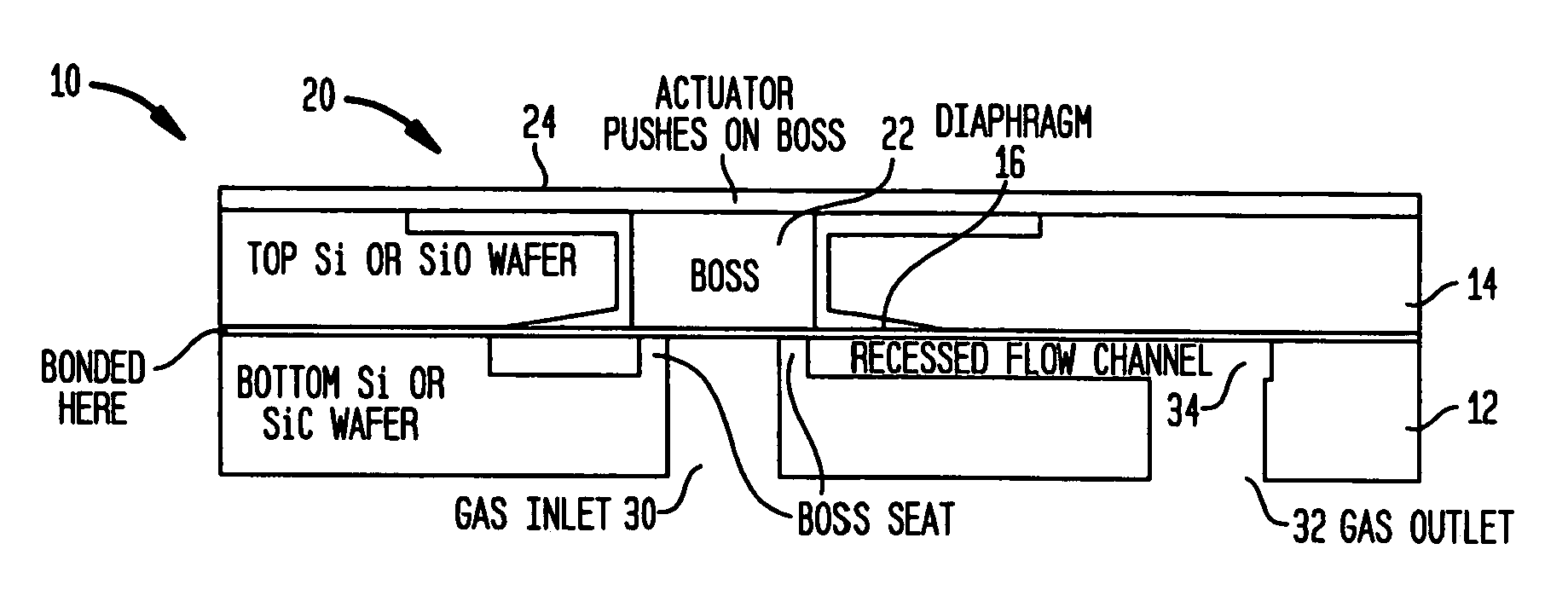
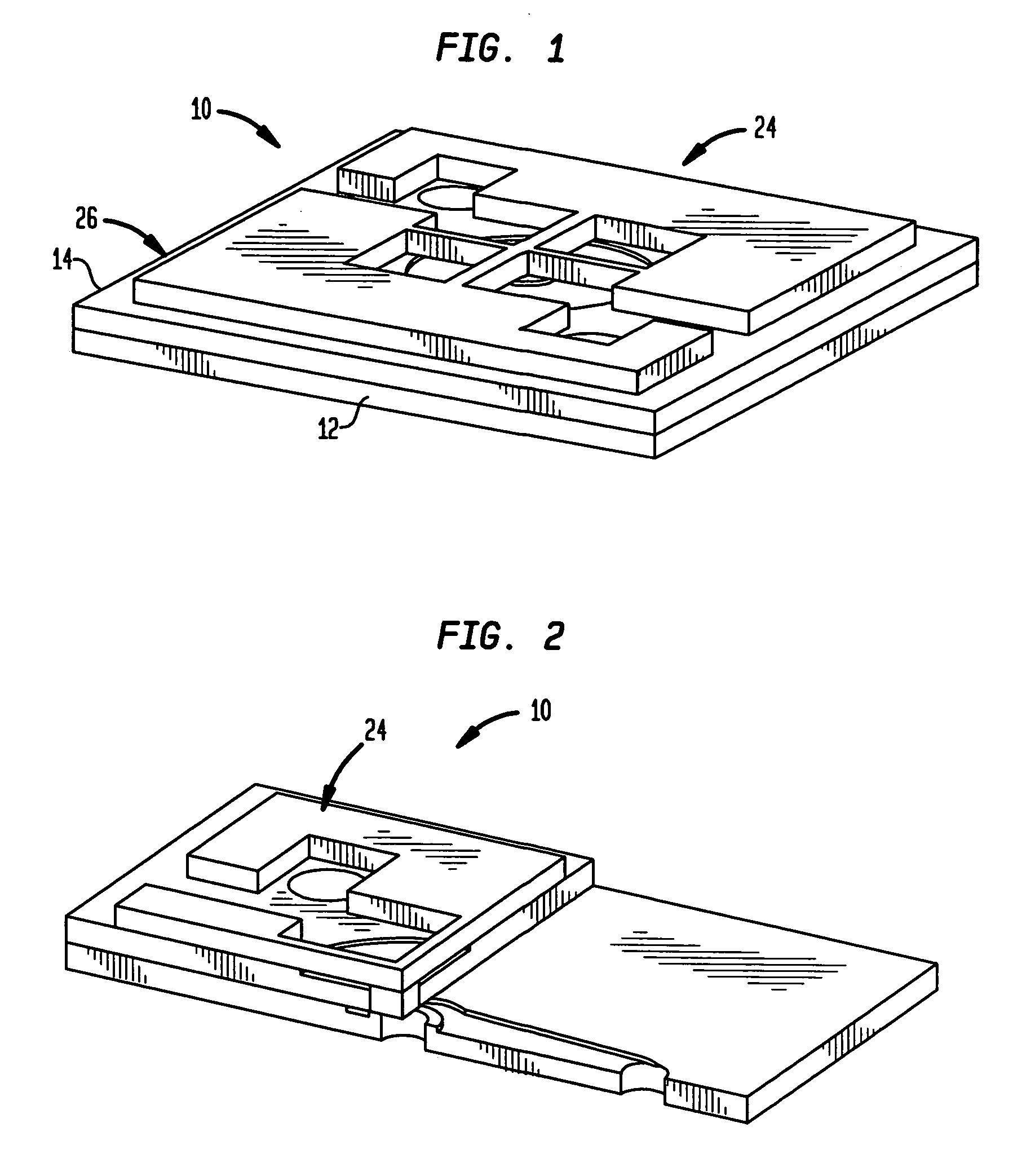
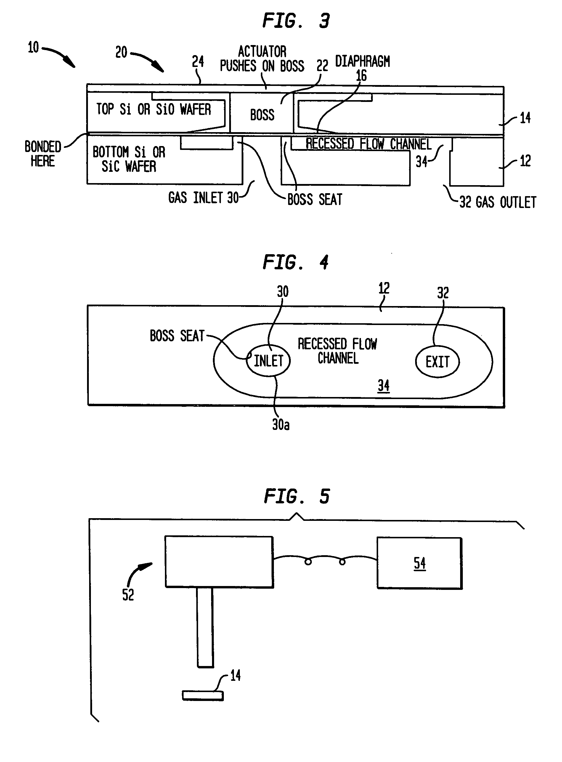
[0023]FIGS. 1–4 show a microvalve 10 generally comprising first and second layers 12 and 14, diaphragm member 16, and switching means 20. Switching means 20, in turn, includes boss 22 and actuation mechanism 24.

[0024]Generally, each of the layers 12 and 14 has a flat thin shape, and the layers are secured together to form a plate or valve body 26. This valve body forms an inlet opening 30 for receiving fluid, an outlet opening 32 for conducting fluid from the valve body, and a flow channel 34 for conducting fluid from the inlet to the outlet. The diaphragm 16 is disposed between the layers 12 and 14, and is moveable between open and closed positions. In the closed position, the diaphragm 16 blocks the flow of fluid from the inlet 30 to the flow channel 34; and in the open position, the diaphragm allows fluid flow from the inlet into that flow channel, allowing fluid flow from the inlet to the outlet 32 of the microvalve. The diaphragm 16 is biased to the closed position, and moves f...


PUM

PropertyMeasurementUnit
depthaaaaaaaaaa
diameteraaaaaaaaaa
etch rateaaaaaaaaaa

Abstract

A microvalve and a method of forming a diaphragm stop for a microvalve. The microvalve includes a first layer and a diaphragm member to control the flow of fluid through the microvalve. The method comprises the step of forming a contoured shaped recess extending inward from a surface of the layer by using a laser to remove material in a series of areas, at successively greater depths extending inward from said surface. Preferably, the recess has a dome shape, and may be formed by a direct-write laser operated via a computer aided drawing program running on a computer. For example, CAD artwork files, comprising a set of concentric polygons approximating circles, may be generated to create the dome structure. The laser ablation depth can be controlled by modifying the offset step distance of the polygons and equating certain line widths to an equivalent laser tool definition. Preferably, the laser tool definition is combined with the CAD artwork, which defines a laser path such that the resulting geometry has no sharp edges that could cause the diaphragm of the valve to tear or rupture.

Description

CROSS REFERENCE TO RELATED APPLICATION[0001]The present application is a divisional application of U.S. Ser. No. 10 / 277,065, filed Oct. 21, 2002 now U.S. Pat. No. 6,774,337.BACKGROUND OF THE INVENTION[0002]1. Field of the Invention[0003]This invention generally relates to methods for fabricating microvalves. More specifically, the invention relates to procedures for forming a contoured valve stop in a microvalve.[0004]2. Background Art[0005]Microvalves may be used to control the flow of a gas in high temperature, high corrosive environments. In one such microvalve, a thin diaphragm, sandwiched between adjacent SiC or Si layers or wafers, is used to control the flow of gas through the valve. In use, the diaphragm abuts against a seat around an inlet of the valve to close that inlet; and when the pressure of gas in this inlet rises above a given value, the diaphragm flexes upwards, allowing gas flow through the inlet and through the valve.[0006]A cavity or recess is provided inside th...

Claims


Application Information

Patent Timeline
Patent Type & Authority Patents(United States)
IPC IPC(8): B81C1/00F15C5/00F16K99/00
CPCB81C1/00492F15C5/00F16K99/0001F16K99/0015F16K99/0046F16K99/0048F16K2099/0074F16K2099/008
Inventor CLAYDON, GLENN S.BALCH, ERNEST W.
Owner LOCKHEED MARTIN CORP
Why Eureka
Try Eureka