
Connection system for a fluid level measuring device

a fluid level indicator and connection system technology, applied in the direction of liquid/fluent solid measurement, machines/engines, instruments, etc., can solve the problems of increasing the number of runs, increasing the cost of manufacturing steps, and increasing the cost of fluid level indicator systems. , the fluid access route or the path through which the fluid level indicator system accesses the fluid storage compartment is becoming more complex, and the fluid access route is becoming more complex

Inactive Publication Date: 2005-08-30
ORSCHELN PRODS
View PDF79 Cites 8 Cited by
  • Summary
  • Abstract
  • Description
  • Claims
  • Application Information

AI Technical Summary

Problems solved by technology

The actual assembly of these various components involves multiple assembly operations requiring costly, time-consuming, and labor intensive manufacturing steps.
Moreover, the fluid access routes or paths through which the fluid level indicator system accesses the fluid storage compartments are becoming more complex (more twists and turns as well as longer runs), smaller, and more compact.

Method used


Image

  • Connection system for a fluid level measuring device
  • Connection system for a fluid level measuring device
  • Connection system for a fluid level measuring device

Examples


Embodiment Construction

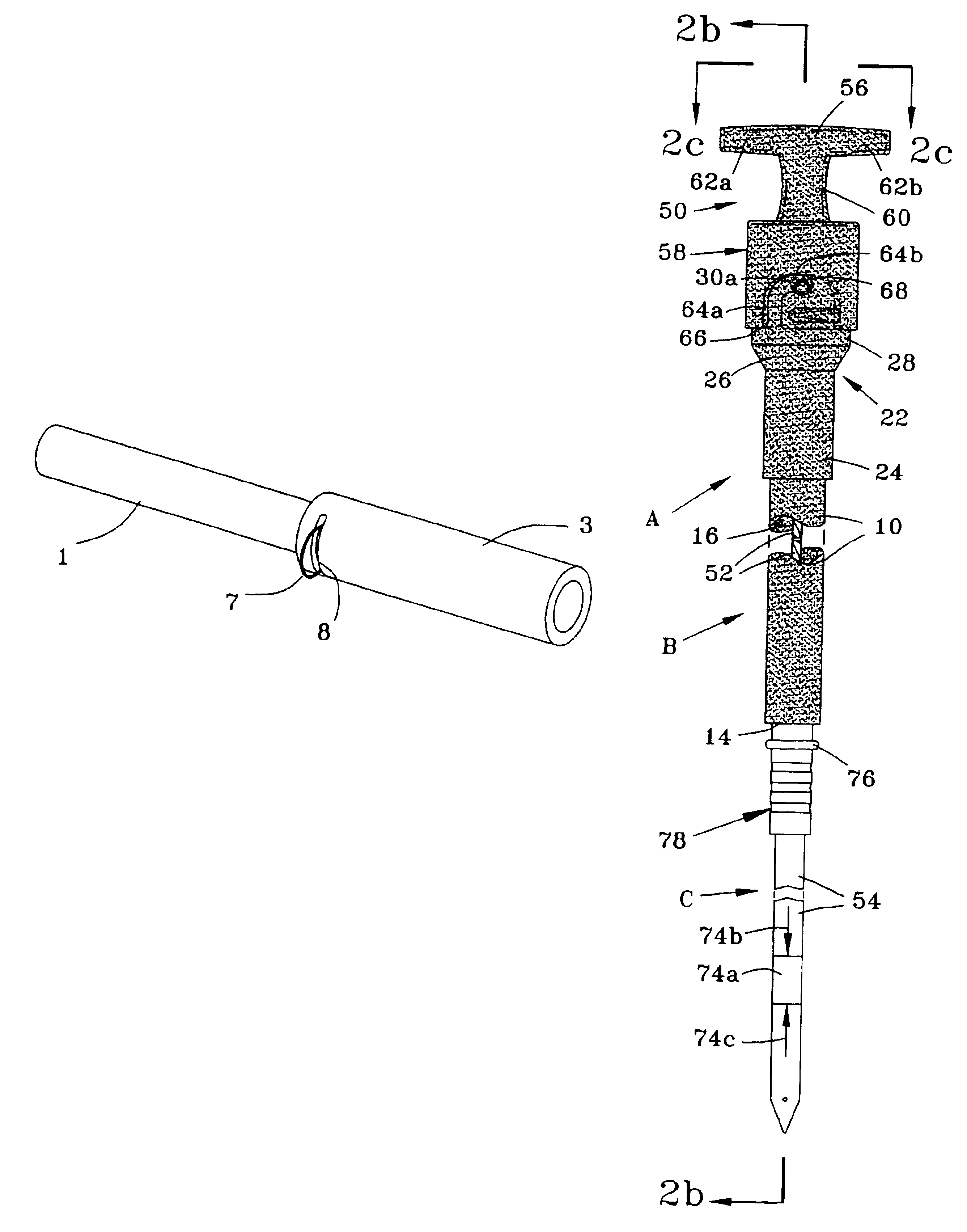
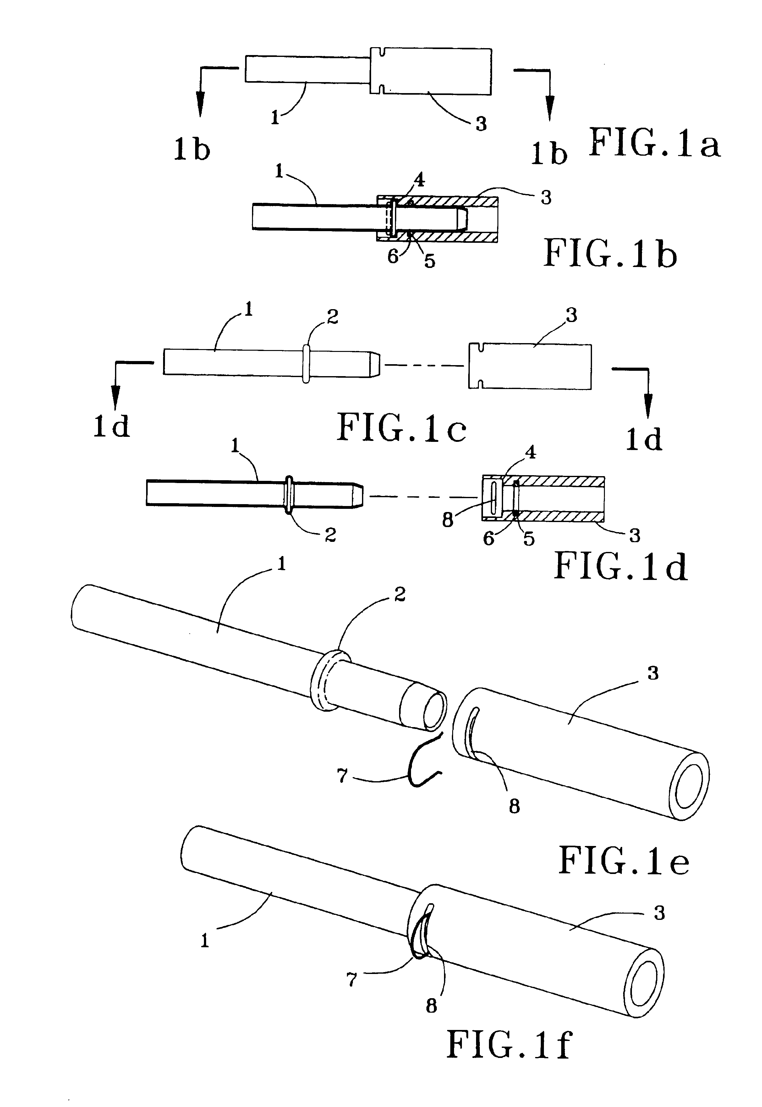
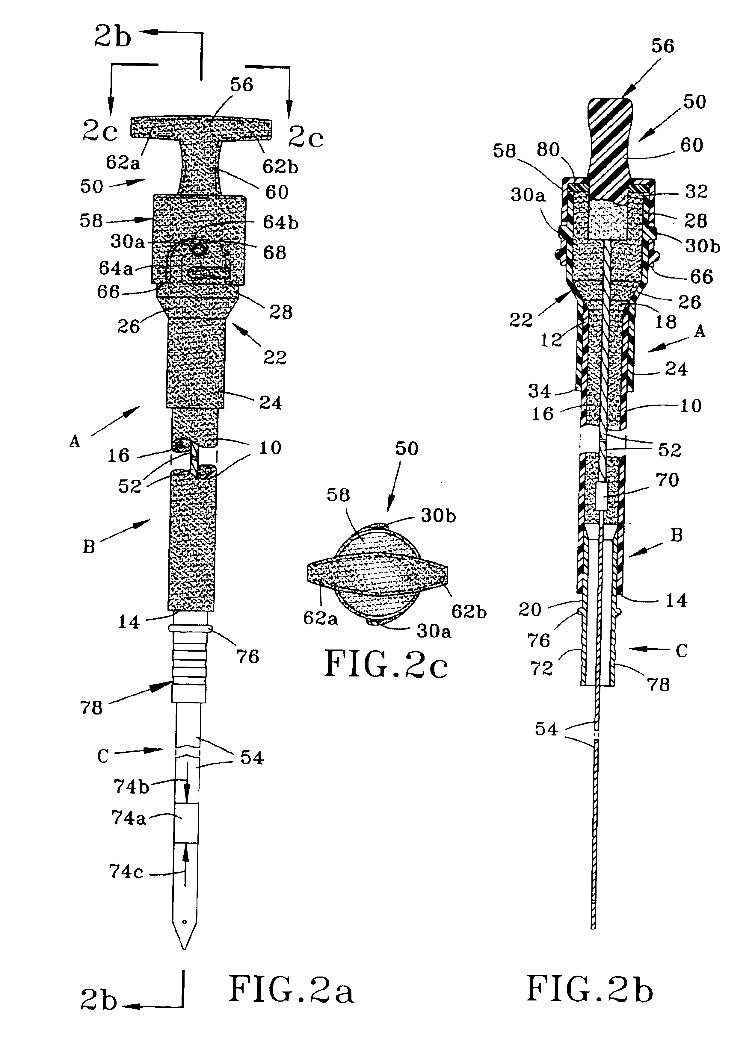
[0015]The instant invention relates to a fluid level indicator system comprising a handle, a shaft (optionally rotatably mounted) and dipstick affixed to the handle, a stationary tube having an opening for receiving the handle (e.g., as illustrated in the patents referenced in the “Background of the Invention”, and Patents and Patent Applications referenced in the “Cross Referenced Patents and Patent Applications”), and a connection system for affixing the stationary tube to a fluid reservoir or another stationary tube that is affixed to the fluid reservoir. The connection system provides fluid passage between the stationary tube and the fluid reservoir or another stationary tube that is affixed to the fluid reservoir. The connection system may also permit the fluid level indicator blade to be inserted into the fluid reservoir.

[0016]The fluid level indicator system can comprise a shaft having a fluid level measuring blade at one end and affixed to a handle on the other. The shaft ca...


PUM


Abstract

A connection system for a fluid level measuring system is disclosed. The disclosed connection system comprises an outer member (also known as a boss), at least one retaining means or clip, and a tube that has been previously shaped and in receptive within the outer member. The end of the tube not received within the outer member is associated with a cap or handle for inserting and removing a fluid level indicator blade (or dipstick).

Description

CROSS-REFERENCE TO RELATED PATENTS AND PATENT APPLICATIONS[0001]The subject matter of the invention is related to U.S. patent application Ser. No. 08 / 976,781, filed on Nov. 24, 1997, entitled “Fluid Level Measuring Device”, now U.S. Pat. No. 6,314,808 B1; U.S. patent application Ser. No. 60 / 221,017, filed on Jul. 27, 2000 and entitled “Fluid Level Measuring Device”; U.S. patent application Ser. No. 60 / 326,636, filed on Oct. 01, 2001 and entitled “Fluid Level Measuring Device”; and U.S. patent application Ser. No. 60 / 347,490, filed on Jan. 09, 2002 and entitled “Fluid Level Measuring Device”. The disclosure of these applications is hereby incorporated by reference.[0002]The subject matter herein claims benefit under 35 U.S.C. 119(e) of U.S. patent application Ser. No. 60 / 297,914, filed on Jun. 13, 2001 and entitled “Connection System For A Fluid Level Measuring Device”; the disclosure of which is hereby incorporated by reference.FIELD OF THE INVENTION[0003]The subject invention is di...

Claims


Application Information

Patent Timeline
IPC IPC(8): G01F23/04G01F23/00
CPCG01F23/04
Inventor DOUGHERTY, JOHN M.SCHMIDT, MICHAEL H.DIERKS, SCOTT A.MAREK, STEVEN W.
Owner ORSCHELN PRODS
Learn More