
Computer chip heat responsive method and apparatus

Inactive Publication Date: 2005-08-23
GLOBALFOUNDRIES US INC
View PDF4 Cites 21 Cited by
  • Summary
  • Abstract
  • Description
  • Claims
  • Application Information

AI Technical Summary

Problems solved by technology

In either event, each island is likely to experience different workloads and thus reach different “hot spot” temperatures.

Method used


Image

  • Computer chip heat responsive method and apparatus
  • Computer chip heat responsive method and apparatus
  • Computer chip heat responsive method and apparatus

Examples


Embodiment Construction

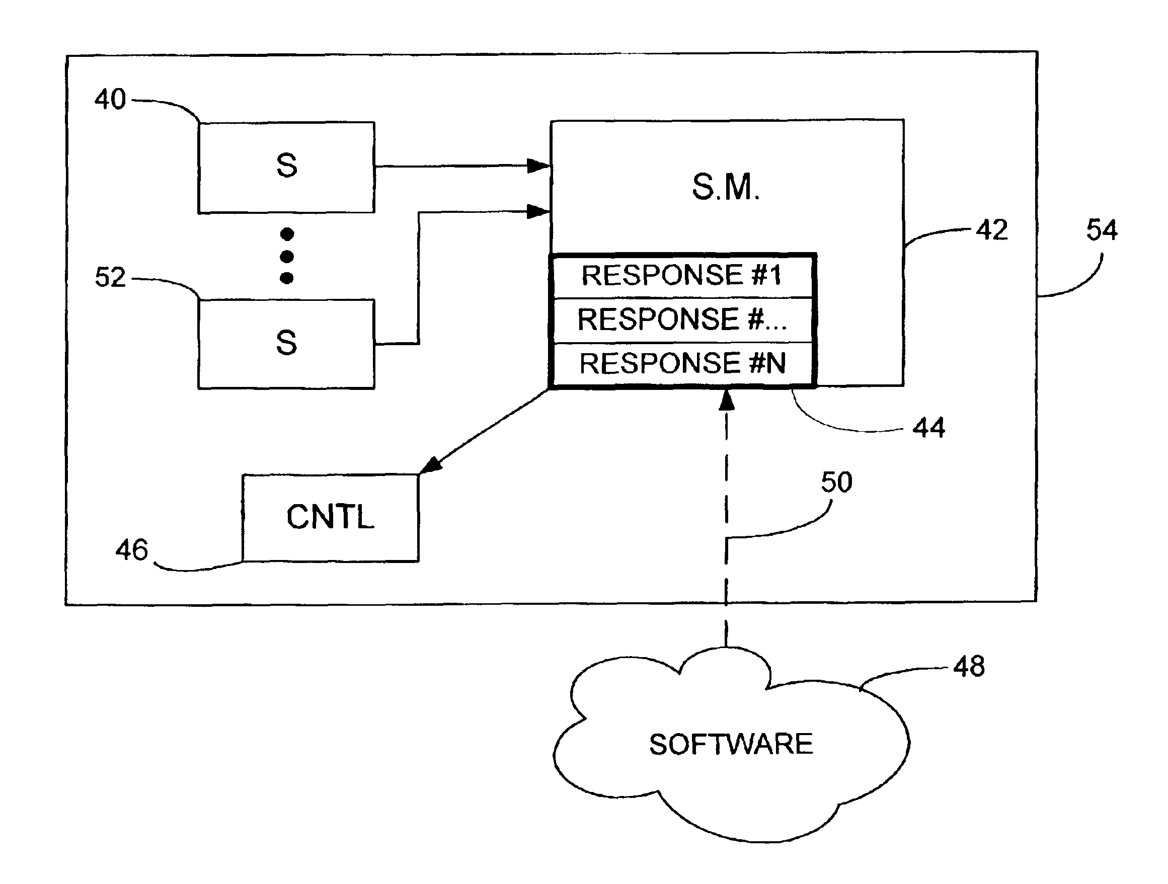
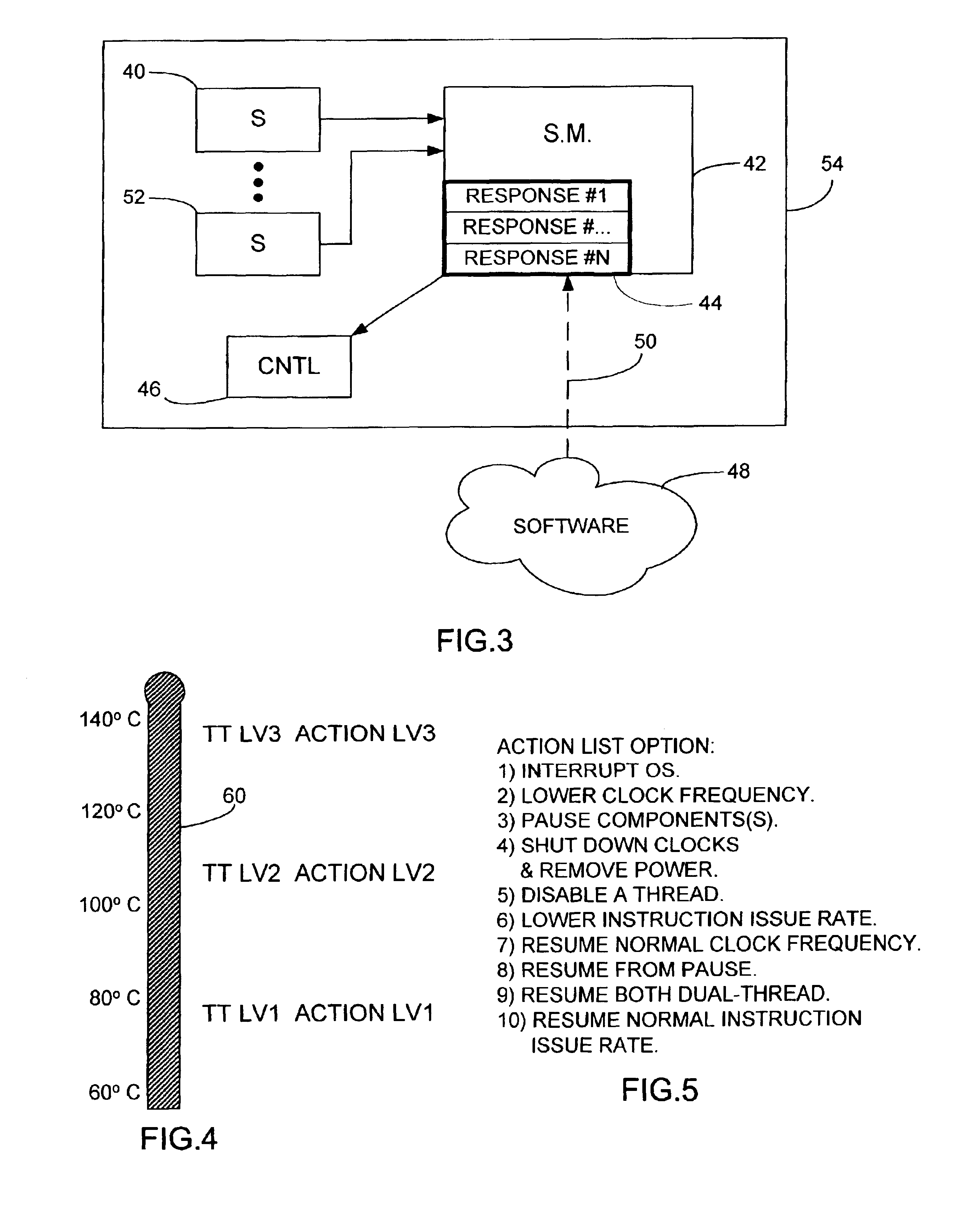
[0013]In the remainder of this description, a processing unit (PU) may be a sole processor of computations in a device. In such a situation, the PU is typically referred to as a CPU (central processing unit). The invention, however, may also be readily practiced on a multiprocessor chip. While the explanation following is directed to sensing a single hot spot of an integrated circuit chip, the invention as practiced will typically have a multiplicity of sensors, each monitoring the temperature of different logic circuits, only some of which may overheat for certain types of computer program operations. As an example, if a program entailed the computation of an extremely large number of consecutively occurring floating point arithmetic operations, the floating point arithmetic logic circuit portion might overheat without causing any other portions to overheat. It should further be noted that the explanation of operation is provided for a single PU controlling operations as concerns o...


PUM


Abstract

Disclosed is an apparatus incorporating hardware based logic and a predetermined default list of software affecting responses to be taken in connection with temperatures sensed by thermal sensors checking the temperature of portions of computer logic. At the time application software is loaded, the software can modify the default response list. The list of responses to be taken and the over temperature conditions at which they are to be activated are stored in hardware directly accessible by hardware based thermal sensor monitoring logic for direct control of the hardware. The control can alter conditions such as clock frequency, stopping use of application software, interrupting OS functionality, removing power from components and so forth.

Description

TECHNICAL FIELD[0001]The invention relates to a PU (processing unit) control and, more particularly, to a method of controlling chip temperature in an operating PU.BACKGROUND[0002]When a program is running in a CPU (Central Processing Unit) or other PU, local hot spots can develop on an integrated circuit chip. Present day chips are configured with islands of circuitry where different islands perform different functions in the PU operation. On a multiprocessor chip, each island may be a separate PU. In either event, each island is likely to experience different workloads and thus reach different “hot spot” temperatures. Known prior art responses comprise shutting down all processing operations of the processor until the chip is adequately cool, decreasing operational workload in a standardized manner for all software used on the PU or increasing the cooling air flow used to lower the temperature of the chip.[0003]It would be desirable if a method could be devised whereby the PU coul...

Claims


Application Information

Patent Timeline
IPC IPC(8): G01K3/00G06F1/20H01L21/822G06F1/00H01L27/04
CPCG01K3/005G06F1/206G06F1/324Y02B60/1217Y02D10/00G02F1/1303G02F1/1335
Inventor CLABES, JOACHIM GERHARDPOWELL, JR., LAWRENCE JOSEPHSTASIAK, DANIEL LAWRENCEWANG, MICHAEL FAN
Owner GLOBALFOUNDRIES US INC
Learn More