
Wireless communication system capable of changing dynamically charge rate and wireless communication unit usable therewith

a wireless communication and dynamic charge technology, applied in telephonic communication, electrical equipment, selection arrangements, etc., can solve the problems of not being able to charge minutely, taking longer time to calculate the charge rate, and complicated charge rate calculation, so as to improve the usability of the wireless communication terminal

Inactive Publication Date: 2005-08-23
CANON KK
View PDF11 Cites 48 Cited by
  • Summary
  • Abstract
  • Description
  • Claims
  • Application Information

AI Technical Summary

Benefits of technology

The present invention provides a method for notifying a wireless communication unit of a changing charge rate from a wireless control station. The method is designed to be optimal and improve the usability of wireless communication terminals used in communication systems where charge rate can change dynamically.

Problems solved by technology

Accordingly, such wireless communication systems do not use dynamic information (a communication traffic volume or a remaining wireless resource amount) as a parameter for changing a charge rate, so that it is not possible to charge minutely depending on a situation for each wireless cell at the place or time where communication occurs.
However, in Japanese Patent Application Laid-Open No. 5-183495 and EP 0597638A1, there is no consideration about how to notify the fee information from a wireless base station to a mobile station.
However, with a method of determining the charge rate in accordance with the amount of service resources including the wired section, as in U.S. Pat. No. 5,303,297 (Japanese Patent Application Laid-Open No. 5-199331), there is the problem that the calculation of charge rate is complicated, and it takes longer time to calculate the charge rate.

Method used


Image

  • Wireless communication system capable of changing dynamically charge rate and wireless communication unit usable therewith
  • Wireless communication system capable of changing dynamically charge rate and wireless communication unit usable therewith
  • Wireless communication system capable of changing dynamically charge rate and wireless communication unit usable therewith

Examples


first embodiment

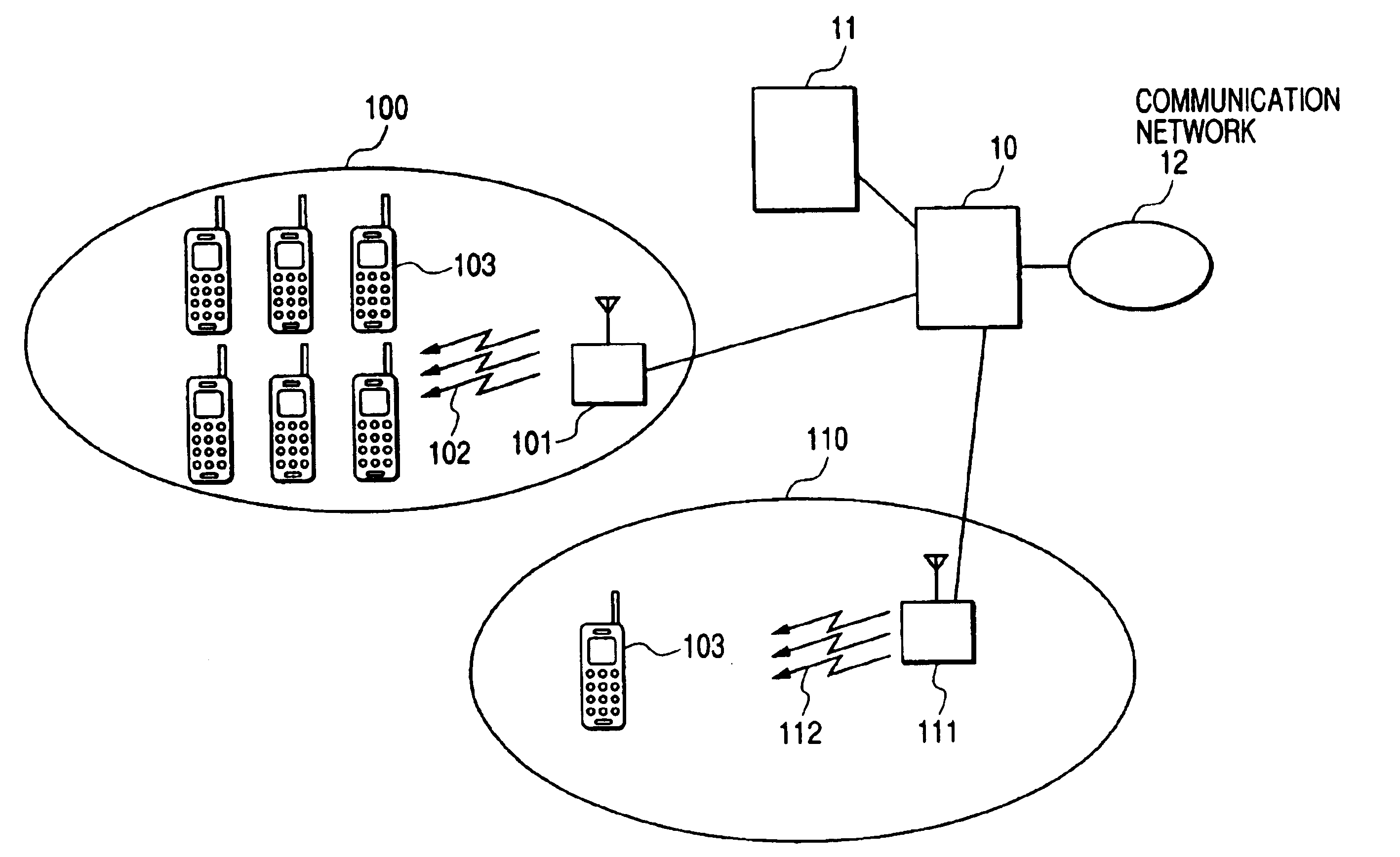
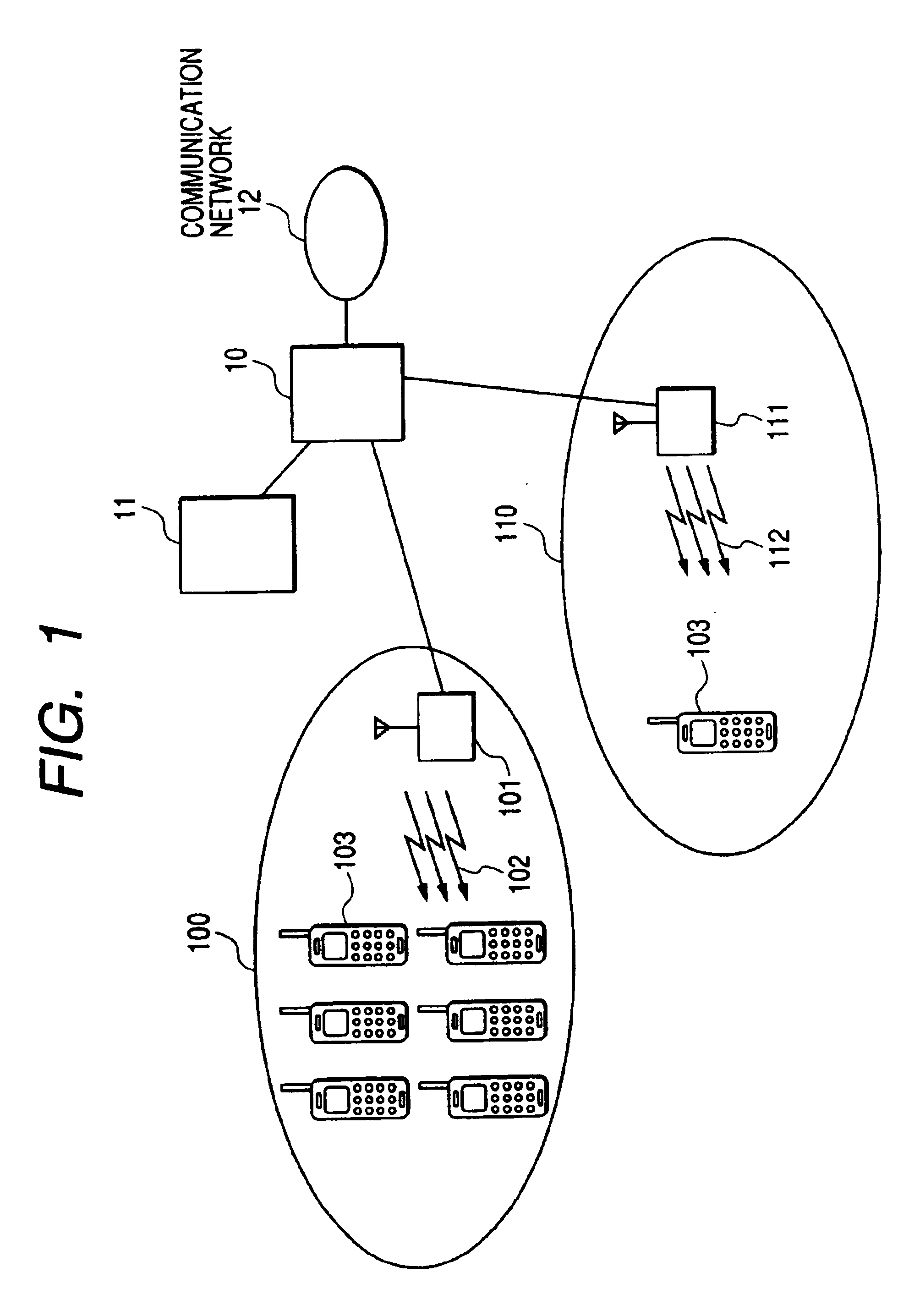
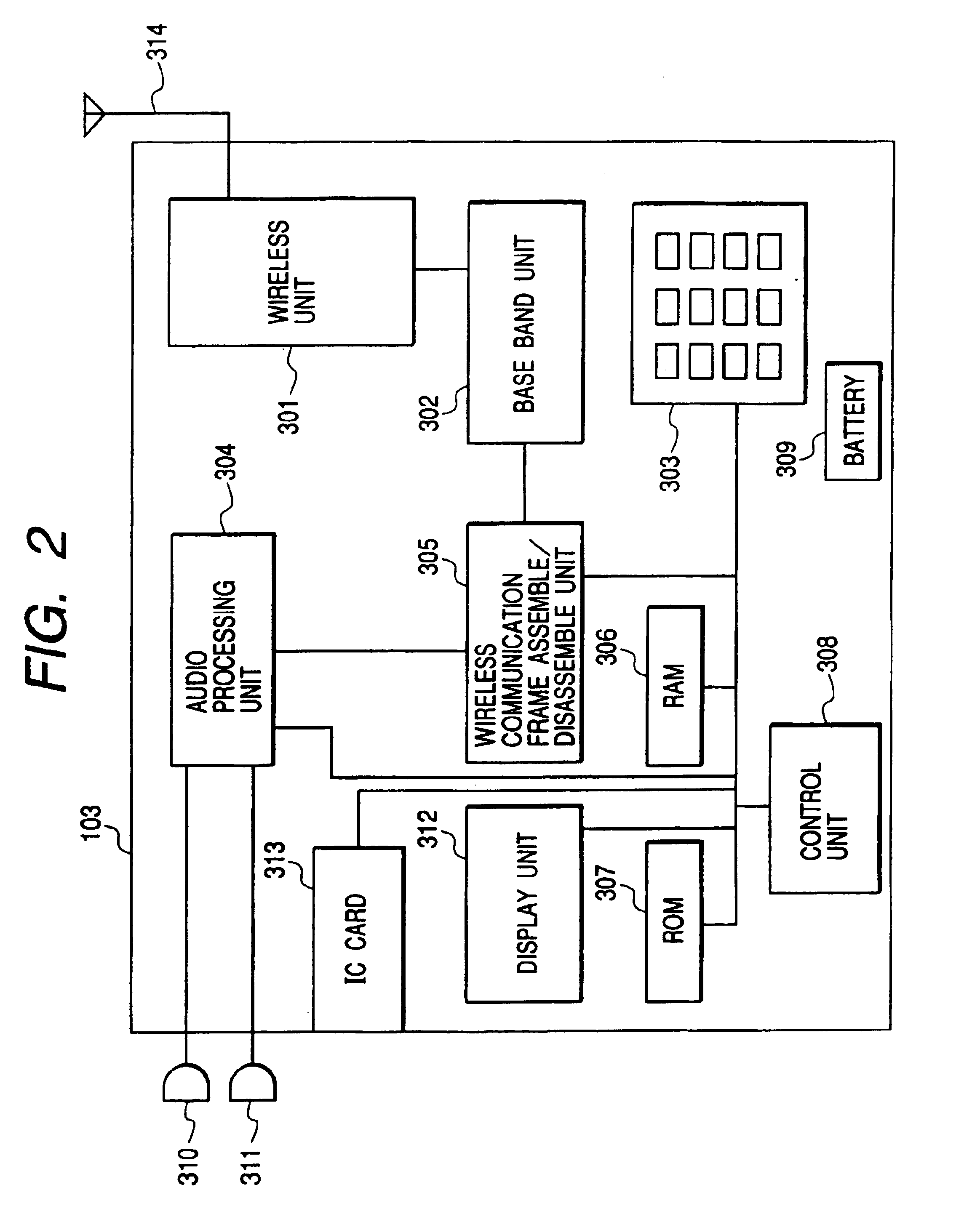
[0041]Referring to FIGS. 1 to 3, a wireless communication system according to a first embodiment of the present invention will be described below. This wireless communication system is presumed to be roaming, and uses a mobile communication system of a wideband CDMA (W-CDMA) (Wideband code division multiple access) which is a candidate for the IMT2000 (International Mobile Telecommunication 2000) system. FIG. 1 is a system configuration view showing the whole of the wireless communication system according to the first embodiment of the invention.

[0042]In FIG. 1, a wireless cell 100 which is controlled by a wireless base station 101 is a cell having a high communication traffic volume (i.e., a high traffic wireless cell) for accommodating a great number of wireless communication terminals 103. In the wireless cell 100, each of the wireless communication terminals 103 is connected to the wireless base station 101 via a wireless communication line. A wireless cell 110 which is controll...

second embodiment

[0057]Referring to FIGS. 5, 7 and 8, explanation will be given below of a processing in which the control unit 407 of the wireless base station 101 in the wireless communication system controls each unit to change the charge rate per unit of time in accordance with a predetermined situation in the wireless cell 100 and notify it to the wireless communication terminal 103 which is communicating according to a second embodiment of the invention. FIG. 7 is a schematic view showing a format of an individual communication information signal on the individual physical channel, which is transmitted from the wireless base station 101 of the wireless communication system according to the second embodiment of the invention.

[0058]In FIG. 7, a frame identification information field 81 indicates that the signal is an individual communication information signal, and an accompanying control information field 82 is an information transmission area for superimposing and transmitting the system contr...

third embodiment

[0066]Referring to FIGS. 5 and 9, explanation will be given below of a processing in which the wireless communication terminal 103 which is waiting receives an informing signal 102 in the wireless cell 100 controlled by the wireless base station 101. FIG. 9 is a flowchart showing a processing in which the wireless communication terminal 103 receives an informing signal 102 while it is waiting according to a third embodiment of the invention. A set allowable charge price 75 (allowable charge rate) which has been preset arbitrarily by the user is stored in the RAM 306 of the wireless communication terminal 103.

[0067]In FIG. 9, the wireless communication terminal 103 which is waiting in the wireless cell 100 controlled by the wireless base station 101 receives an informing signal 102 which is regularly transmitted from the wireless base station 101 (step S901). Then, the present charge rate per unit of time is read from the information field 253 of charge rate per unit of time in the w...


PUM


Abstract

The invention aims at providing a method of notifying a charge rate from a wireless controller to a wireless communication unit when the charge rate is changed dynamically.According to the invention, there is provided a wireless communication system having a wireless controller for controlling a wireless communication unit. The wireless communication system is composed of determination means for determining a situation within a wireless cell controlled by the wireless controller, memory means for storing a threshold for changing the charge rate for communication within the wireless cell, the threshold having a hysteresis characteristic, and decision means for deciding the charge rate for communication within the wireless cell based on the situation determined by the determination means and the threshold having the hysteresis characteristic stored in the memory means.

Description

BACKGROUND OF THE INVENTION[0001]1. Field of the Invention[0002]The present invention relates to a wireless communication system and a wireless communication terminal, and more particularly to a wireless communication system capable of changing dynamically a charge rate and a wireless communication unit which can be used in the wireless communication system.[0003]2. Related Background Art[0004]Conventional cellular wireless communication systems for public use, relying on a micro cell or the like, including PDC (Personal Digital Cellular), PHS (Personal Handyphone System), and GSM (Global System for Mobile communications), make use of, as a parameter for changing the communication fee (charge rate), static information such as a charge condition (service plan) agree upon when the user of a wireless communication terminal subscribes the service provided by a carrier, or communication time.[0005]Accordingly, such wireless communication systems do not use dynamic information (a communic...

Claims


Application Information

Patent Timeline
Patent Type & Authority Patents(United States)
IPC IPC(8): H04M15/00H04Q7/38H04M15/28H04W4/24
CPCH04M15/00H04M15/43H04M15/44H04M15/8016H04M15/8022H04M15/8027H04M15/8044H04M15/81H04M15/83H04M15/8353H04M2215/0104H04M2215/0112H04M2215/2006H04M2215/32H04M2215/42H04M2215/7414H04M2215/7421H04M2215/7428H04M2215/745H04M2215/7806H04M2215/7886H04M2215/8112H04M2215/8154H04M2215/82
Inventor HAMADA, MASASHI
Owner CANON KK
Learn More