Eureka AIR delivers breakthrough ideas for toughest innovation challenges, trusted by R&D personnel around the world.

Exhaust unit for engines particularly for high-performance vehicles

a technology for exhaust systems and high-performance vehicles, which is applied to engine components, machines/engines, and silos. it can solve the problems of difficult integration within the vehicle, large volume of exhaust systems designed to optimize engine performance, and general bulkiness, and achieve the effect of improving ease of installation

Inactive Publication Date: 2005-08-23
SUPERSPRINT
View PDF7 Cites 6 Cited by
  • Summary
  • Abstract
  • Description
  • Claims
  • Application Information

AI Technical Summary

Benefits of technology

[0008]It is the main object of the invention to provide an exhaust unit for thermic engines which has the features that are normally required in high-performance vehicles, while providing a better ease of installation, and more particularly dispensing with the need to remove the engine.
[0010]A further object of the invention is to provide an exhaust unit having a cost comparable to prior units and which is easy to manufacture, and, moreover, which can be manufactured by procedures known and already in use in the art.

Problems solved by technology

Exhaust systems designed to optimize the engine's performance according to the above criteria are generally quite bulky and, particularly in view of their monolithic structure, difficult to integrate within the vehicle, which is normally designed for standard exhausts.
Consequently, their installation involves disassembling the engine, which is a difficult and time-consuming job.
This requirement has not been satisfactorily met until now, on the one hand, due to the difficulty of inserting flexible components in the pipes because of their high operating temperatures, which do not allow synthetic materials to be used, and, on the other hand, due to the requirement of maintaining a perfect seal in the joints, in order to avoid gas leaks in intermediate areas of the unit.

Method used


Image

  • Exhaust unit for engines particularly for high-performance vehicles
  • Exhaust unit for engines particularly for high-performance vehicles
  • Exhaust unit for engines particularly for high-performance vehicles

Examples


Embodiment Construction

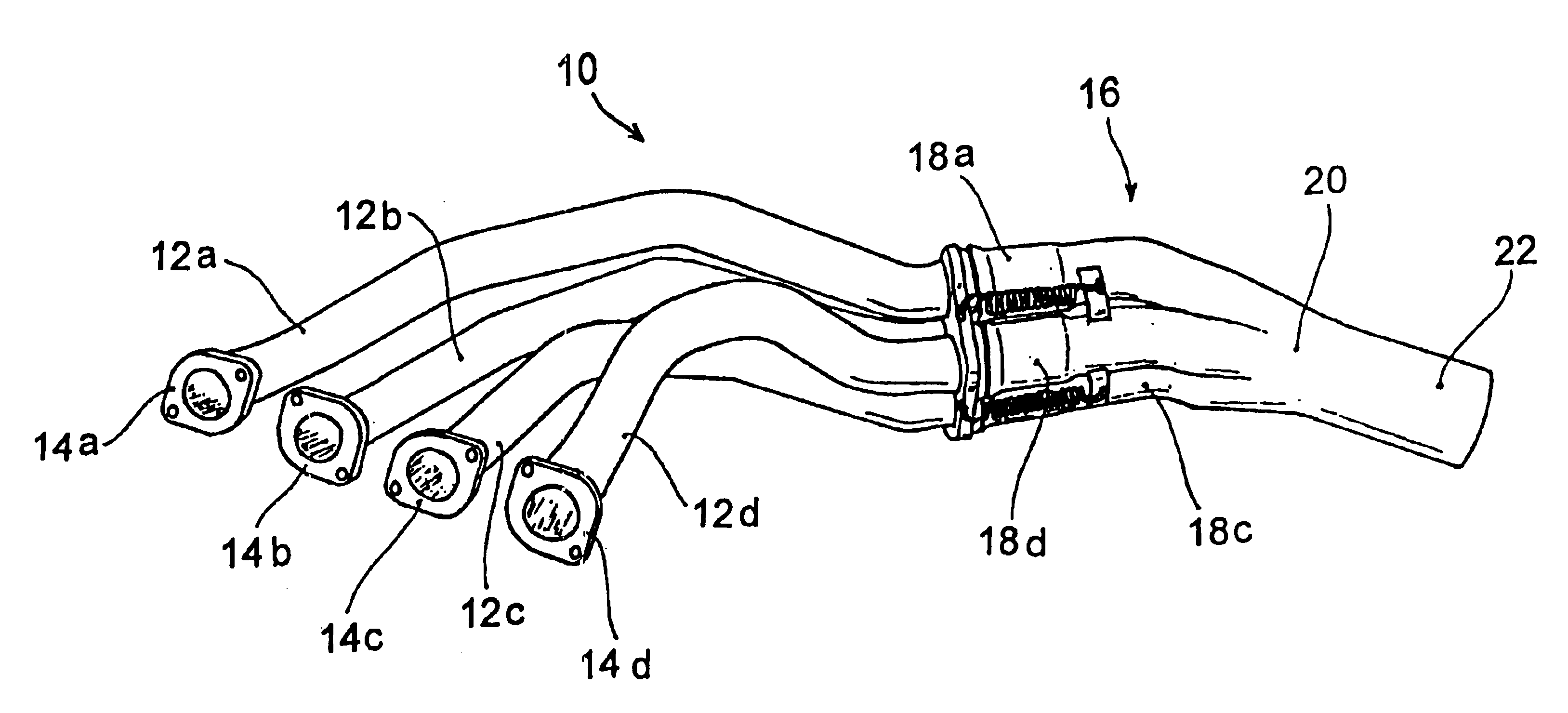
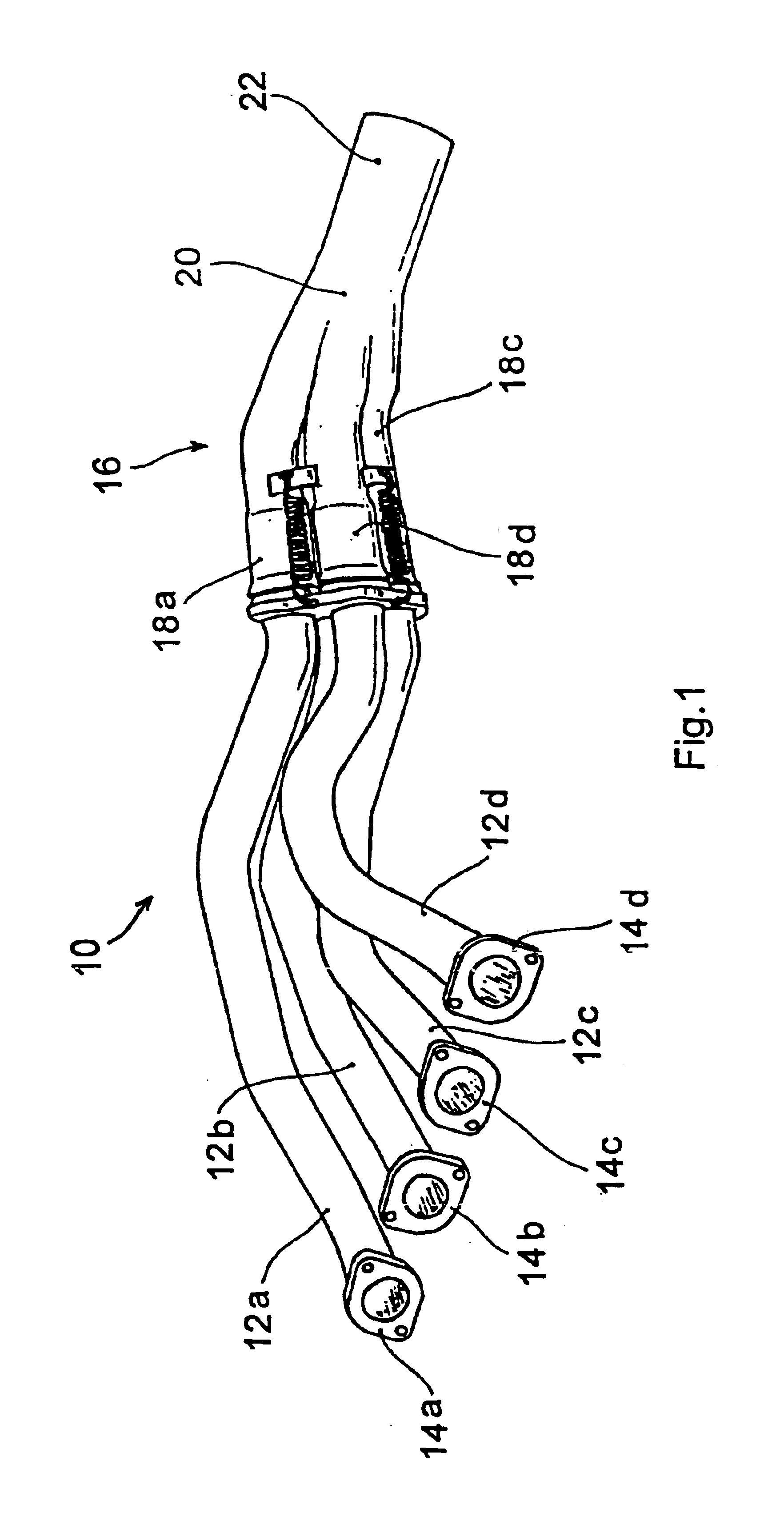
[0018]With reference to the above listed Figures, these show an exhaust unit 10 jointable to an engine having four cylinder in line comprising four pipes 12a,b,c,d, provided with flanges 14a,b,c,d for jointing to the exhaust ports of the engine, which four pipes join together into a manifold 16, as described below in more detail.

[0019]Pipes 12a,b,c,d are shaped so that their lengths are substantially similar, and accordingly they include bent sections which are most visible in pipe 12d, which connects to the engine near manifold 16 and consequently requires several bends in order to make the gas path longer.

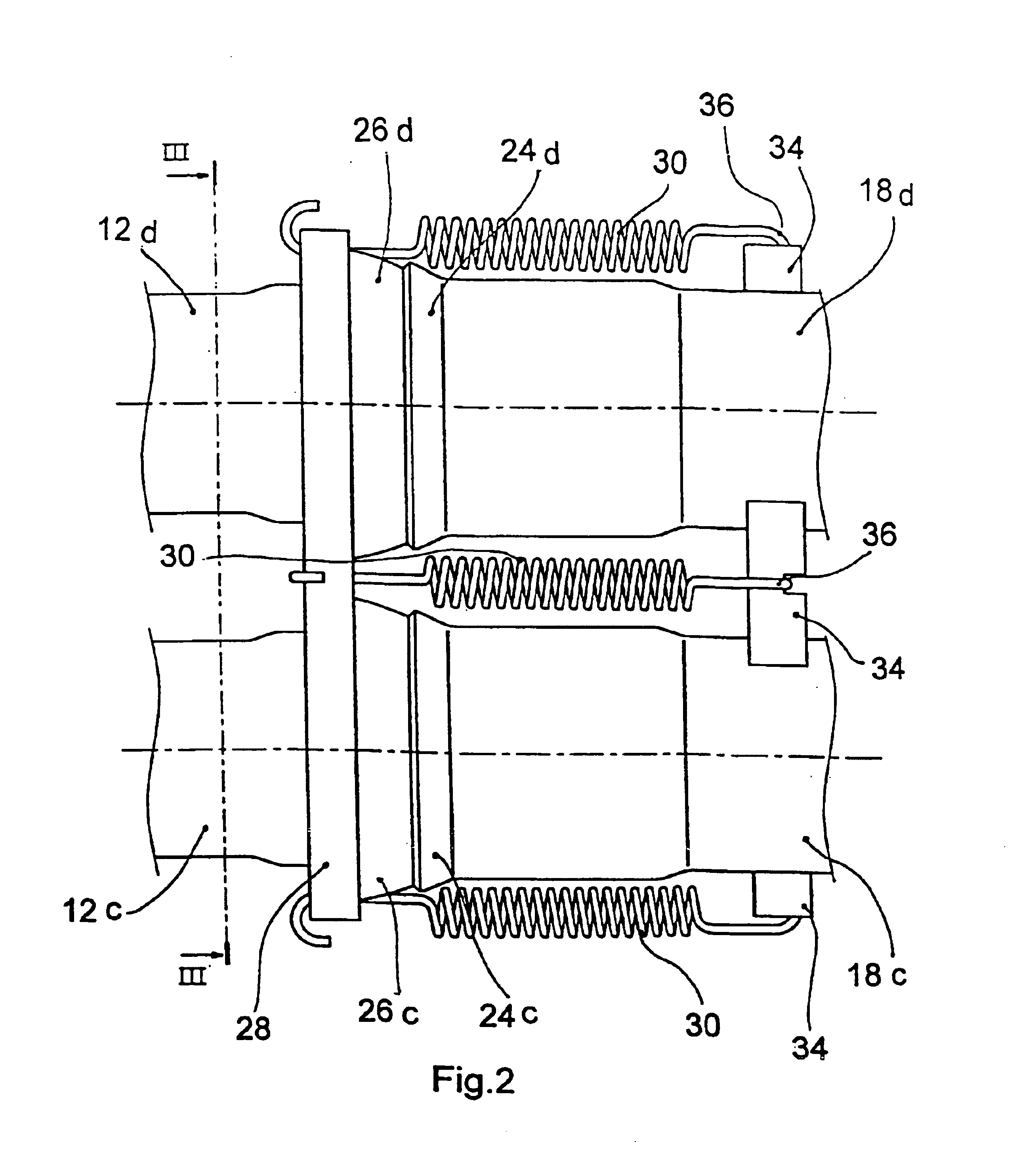
[0020]Manifold 16 comprises four pipe stubs 18a,b,c,d, into which the respective pipes 12a,b,c,d are inserted. Stubs 18a,b,c,d lead to a box 20, from which extends a single conduit 22. Conduit 22 can be jointed to the terminal parts of the exhaust system. Advantageously, both the stub pipes and the conduit extend in substantially parallel directions.

[0021]According to the inventi...


PUM


Abstract

A plurality of pipes adapted to be jointed to the exhaust ports of one line of an engine are joined together into a manifold comprising an equal number of pipe stubs, each receiving one of said pipes. The pipe stubs lead to a box from which extends a conduit that is jointable to terminal parts of the exhaust system, and each of them is flared at its jointed end, against which an annular gasket surrounding the respective pipe is pressed to abut by elastic elements.

Description

[0001]This invention is concerned with an exhaust unit for engines, particularly for high-performance vehicles.BACKGROUND OF THE INVENTION[0002]Exhaust units in internal-combustion engines as used today comprise a set of pipes which can be jointed to exhaust ports of the engine, which in turn converge into a single end conduit leading to a catalyzer or, in sports cars, directly to a silencer.[0003]Particularly in high-performance engines, such as used in sports and competitions, it is important to design the exhaust system appropriately, with special regard to the dynamics and resistance of the gas flow, since these factors may considerably affect the engine's performance.[0004]With reference to this, it has been found expedient that the exhaust gases from the different cylinders follow paths of substantially equal lengths, and that the pipes fit into the terminal exhaust tube with smooth angles, in order to avoid local resistances to the gas flow. In general, the aim is to favor th...

Claims


Application Information

Patent Timeline
Patent Type & Authority Patents(United States)
IPC IPC(8): F01N7/10F01N7/18F01N13/08F01N13/10F01N13/18
CPCF01N13/10F01N13/1811
Inventor GILLI, ALESSANDRO
Owner SUPERSPRINT
Why Eureka
Eureka Blog
Learn More