Supercharge Your Innovation With Domain-Expert AI Agents!

Coding device and coding method

a coding device and video signal technology, applied in the field of coding devices and coding methods for video signals, can solve the problem that the length limit of video packets cannot be maintained, and achieve the effect of avoiding overflow of the vbv buffer

Inactive Publication Date: 2005-08-16
MITSUBISHI ELECTRIC CORP
View PDF12 Cites 6 Cited by
  • Summary
  • Abstract
  • Description
  • Claims
  • Application Information

AI Technical Summary

Benefits of technology

[0053]According to the present invention, the above-mentioned structure can give the following effects.
[0067]According to the thirteenth aspect of the present invention, the bit rate R at which a code stored at the step (d) is read is variable. Therefore, the underflow of the second storing means or the overflow of the VBV buffer can be avoided effectively.

Problems solved by technology

On condition that a limit is set to a capacity per video packet and the video packet having only the stuffing is prohibited, there has conventionally been a problem in that the length limit of the video packet cannot be maintained or the video packet having only the stuffing is generated.

Method used


Image

  • Coding device and coding method
  • Coding device and coding method
  • Coding device and coding method

Examples


first embodiment

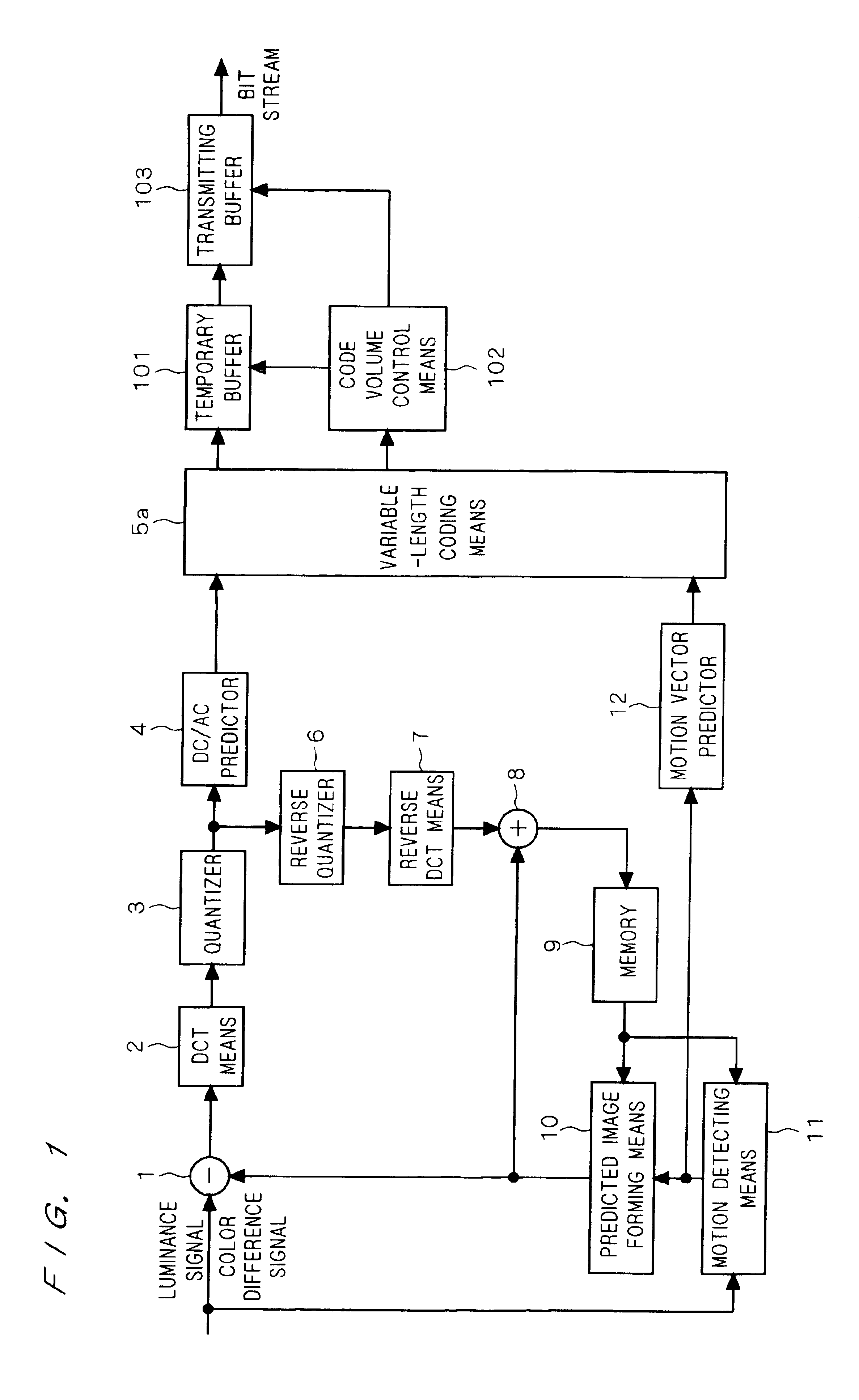
[0082]FIG. 1 shows a coding device according to a first embodiment of the present invention. In FIG. 1, the reference numeral 1 denotes a subtracter for receiving an external input signal as a first input. An output of the subtracter 1 is input to a DC / AC predictor 4 and a reverse quantizer 6 through DCT means 2 and a quantizer 3. An output of the DC / AC predictor 4 is sent to a first input of variable—length coding means 5a.

[0083]On the other hand, an output of the reverse quantizer 6 is sent to a first input of an adder 8 through reverse DCT means 7. An output of the adder 8 is sent to a memory 9, and an output of the memory 9 is sent to a first input of predicted image forming means 10 and a first input of motion detecting means 11.

[0084]The external input signal is sent to a second input of the motion detecting means 11, and an output of the motion detecting means 11 is sent to a second input of the predicted image forming means 10 and a motion vector predictor 12. An output of ...


PUM


Abstract

To provide a coding device which does not generate a video packet having only a stuffing but can insert a minimum stuffing to prevent an underflow of a buffer in the case in which a video packet has a length limit. A minimum code volume (Tmin) is set for each VOP and a break of a video packet and an insertion of a stuffing are determined such that a code volume (Sc) of the VOP is not smaller than the minimum code volume (Tmin).

Description

BACKGROUND OF THE INVENTION[0001]1. Field of the Invention[0002]The present invention relates to a coding device and a coding method for coding a video signal by using a video packet having a length limit set thereto which is related to a portable telephone, a TV telephone system and the like, for example.[0003]2. Description of the Background Art[0004]FIG. 6 is a block diagram showing a conventional coding device described in “Everything about MPEG-4” (Institute of Industrial Research) P. 39 to P. 40, for example, FIG. 7 is a diagram illustrating an input signal of the conventional coding device, FIGS. 8A to 8D are diagrams illustrating a structure of a bit stream, and FIG. 9 is a diagram illustrating a position (arrangement) of a video packet over a screen (display state).[0005]In FIG. 6, the reference numeral 1 denotes a subtracter for receiving an external input signal (a luminance signal, a color difference signal or the like) sent externally as a first input. An output of the ...

Claims


Application Information

Patent Timeline
Patent Type & Authority Patents(United States)
IPC IPC(8): H04N7/24H04N7/26H04N7/50H04N7/30
CPCH04N21/23406H04N21/235H04N21/435H04N21/44004H04N19/139H04N19/176H04N19/70H04N19/15H04N19/115H04N19/61H04N19/60H04N19/186H04N19/18H04N19/91
Inventor HATANO, YOSHIKOKIJIMA, JUNKOINAMURA, MAMORUIKEDA, TOMOAKISUGIYAMA, KAZUHIORO
Owner MITSUBISHI ELECTRIC CORP
Features
  • R&D
  • Intellectual Property
  • Life Sciences
  • Materials
  • Tech Scout
  • Unparalleled Data Quality
  • Higher Quality Content
  • 60% Fewer Hallucinations
Learn More