
Method and apparatus for reducing false hook detection

a false hook and detection method technology, applied in the field of telecommunications, can solve the problems of false hook detection, undesirable transients of switching between the three states, etc., and achieve the effects of disabling switch hook detection, and reducing false hook detection

Inactive Publication Date: 2005-08-16
MICROSEMI SEMICON U S
View PDF6 Cites 0 Cited by
  • Summary
  • Abstract
  • Description
  • Claims
  • Application Information

AI Technical Summary

Benefits of technology

This approach effectively minimizes transient-related false hook detection, ensuring reliable ring-trip and AC fault detection, and supports high-bandwidth data transfer by stabilizing DC conditions during state transitions.

Problems solved by technology

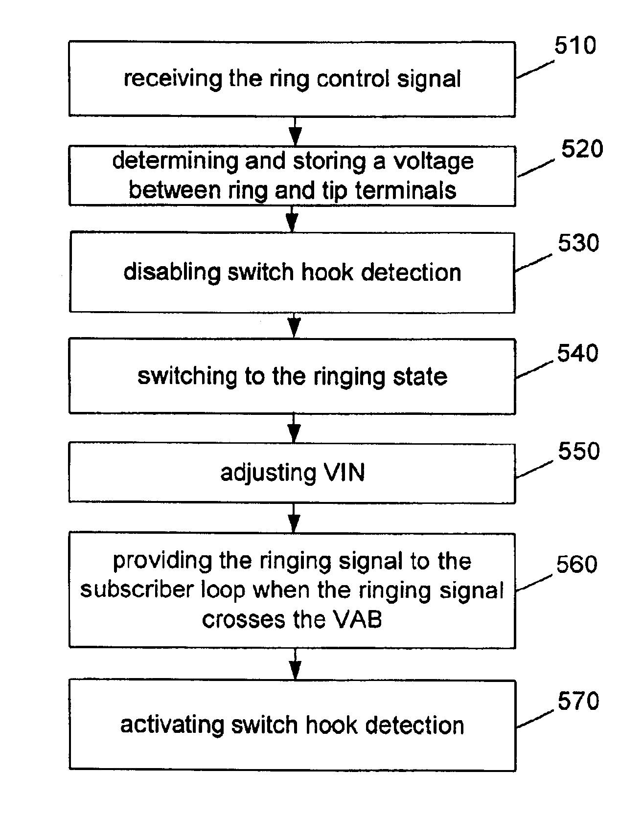
Switching between the three states may give rise to undesirable transients, partly because of the varying level of currents in the different modes.
As a result, the undesirable transients may adversely affect the operation of the SLIC, resulting in false hook detection, for example.

Method used


Image

  • Method and apparatus for reducing false hook detection
  • Method and apparatus for reducing false hook detection
  • Method and apparatus for reducing false hook detection

Examples


Embodiment Construction

[0022]Illustrative embodiments of the invention are described below. In the interest of clarity, not all features of an actual implementation are described in this specification. It will of course be appreciated that in the development of any such actual embodiment, numerous implementation-specific decisions must be made to achieve the developers' specific goals, such as compliance with system-related and business-related constraints, which will vary from one implementation to another. Moreover, it will be appreciated that such a development effort might be complex and time-consuming, but would nevertheless be a routine undertaking for those of ordinary skill in the art having the benefit of this disclosure.

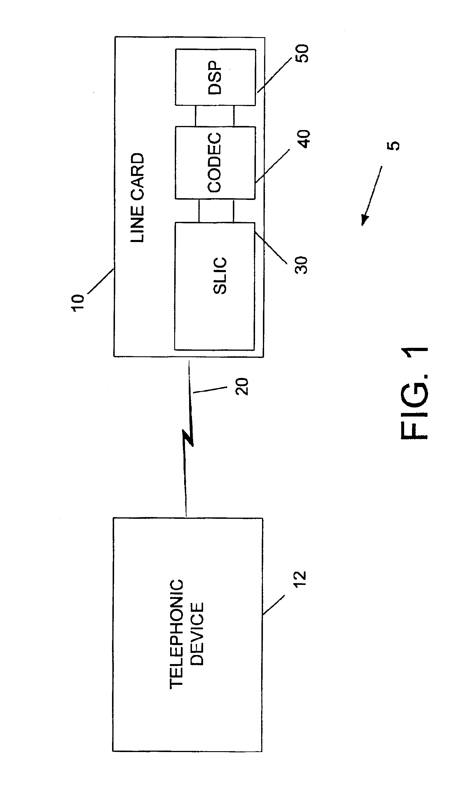
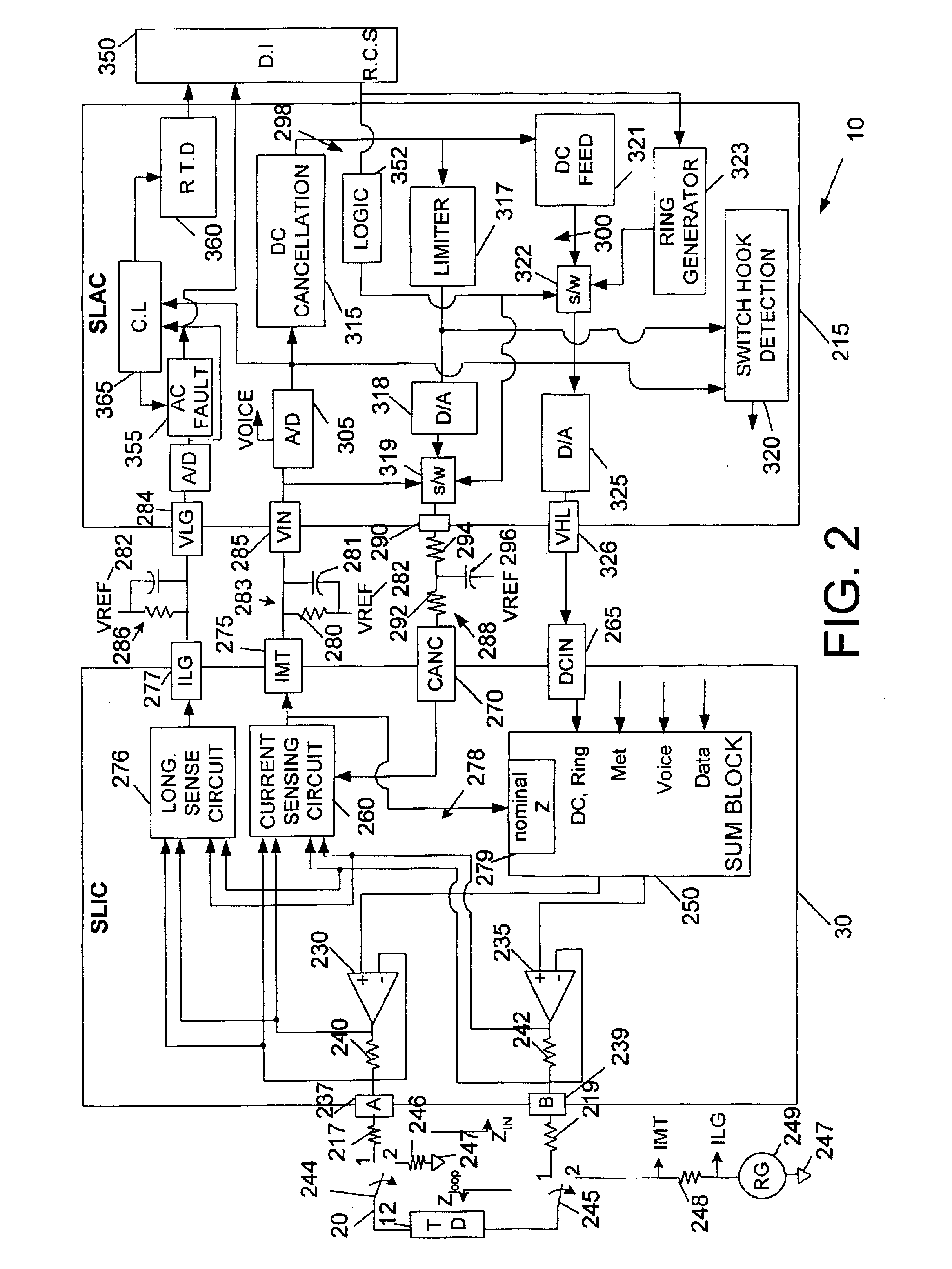
[0023]Referring first to FIG. 1, a simplified block diagram of a communications system 5 in accordance with the present invention is provided. The communications system 5 includes a line card 10 that interfaces with a telephonic device 12 over a subscriber line 20. In an actual i...


PUM


Abstract

A method and apparatus is provided reducing false switch hook detection in a line card coupled to a subscriber loop. The method comprises operating in a first state of the line card, receiving a control signal, and disabling switch hook detection in the line card. The method further comprises determining an initial condition of a second state of the line card, operating in the second state of the line card in response to receiving the control signal, wherein the second state begins to operate from the determined initial condition. The switch hook detection in the line card is activated.

Description

BACKGROUND OF THE INVENTION[0001]1. Field of the Invention[0002]This invention relates generally to telecommunications, and, more particularly, to a method and apparatus for reducing false hook detection in a line card.[0003]2. Description of the Related Art[0004]In communications systems, particularly telephony, it is a common practice to transmit signals between a subscriber station and a central switching office via a two-wire bi-directional communication channel. A line card generally connects the subscriber station to the central switching office through a subscriber line. At the subscriber end, a telephonic device may be employed to establish communication with a remote user using the subscriber line. The combination of the telephonic device and the subscriber line is commonly referred to as a subscriber loop.[0005]A line card generally includes at least one subscriber line interface circuit (SLIC) as well as a subscriber line audio-processing circuit (SLAC). The SLIC interfac...

Claims


Application Information

Patent Timeline
Patent Type & Authority Patents(United States)
IPC IPC(8): H04M1/738H04M3/22H04M3/14H04M3/08
CPCH04M1/738H04M3/2272H04M3/14
Inventor LI, JIN
Owner MICROSEMI SEMICON U S
Learn More