
Connector for making an optical connection underwater

Inactive Publication Date: 2005-08-16
SIEMENS ENERGY GLOBAL GMBH & CO KG
View PDF9 Cites 46 Cited by
  • Summary
  • Abstract
  • Description
  • Claims
  • Application Information

AI Technical Summary

Benefits of technology

[0009]By arranging the optical path to extend through a side of the probe and preferably at a slant to the axial direction, rather than having axially directed optical end faces, the risk of damage or signal attenuation caused by particles of sand, silt or the like being trapped between such end faces is minimised.
[0034]It is preferred for the chamber of the second connector part and the chamber of the first connector part to be sealed from each other when the first and second connector parts are interengaged. This improves the sealing properties of the connector. In particular, if the integrity of the probe chamber is compromised, this will not affect the integrity of the chamber of the second connector, where the optical coupling will normally be established.

Problems solved by technology

However, with such an arrangement there is a risk of damage to the optical end faces of the optical fibres caused by particles of sand, silt or the like which have lodged on the seal members.
With such an arrangement, if the ambient water contains debris such as sand, silt or the like, then there is again a risk that particles of debris will lodge against the end face of the wand supported optical fibre and then be carried forward along the oil-filled tube to be sandwiched between that end face and the end face of the other optical fibre.
Further, the mechanism and sealing arrangement is complex which is not desirable in subsea operations.
Although these known proposals avoid the problem of debris becoming lodged on an axial end face of an optical member when it emerges from its housing, they rely on the effectiveness of the wiping action, and if the wipers deteriorate with time the optical coupling may become contaminated.
Moreover, in the connected condition of the connector, the region where the optical coupling is made is not sealed from the outside and may therefore be subject to entry of contaminants.

Method used


Image

  • Connector for making an optical connection underwater
  • Connector for making an optical connection underwater
  • Connector for making an optical connection underwater

Examples


Embodiment Construction

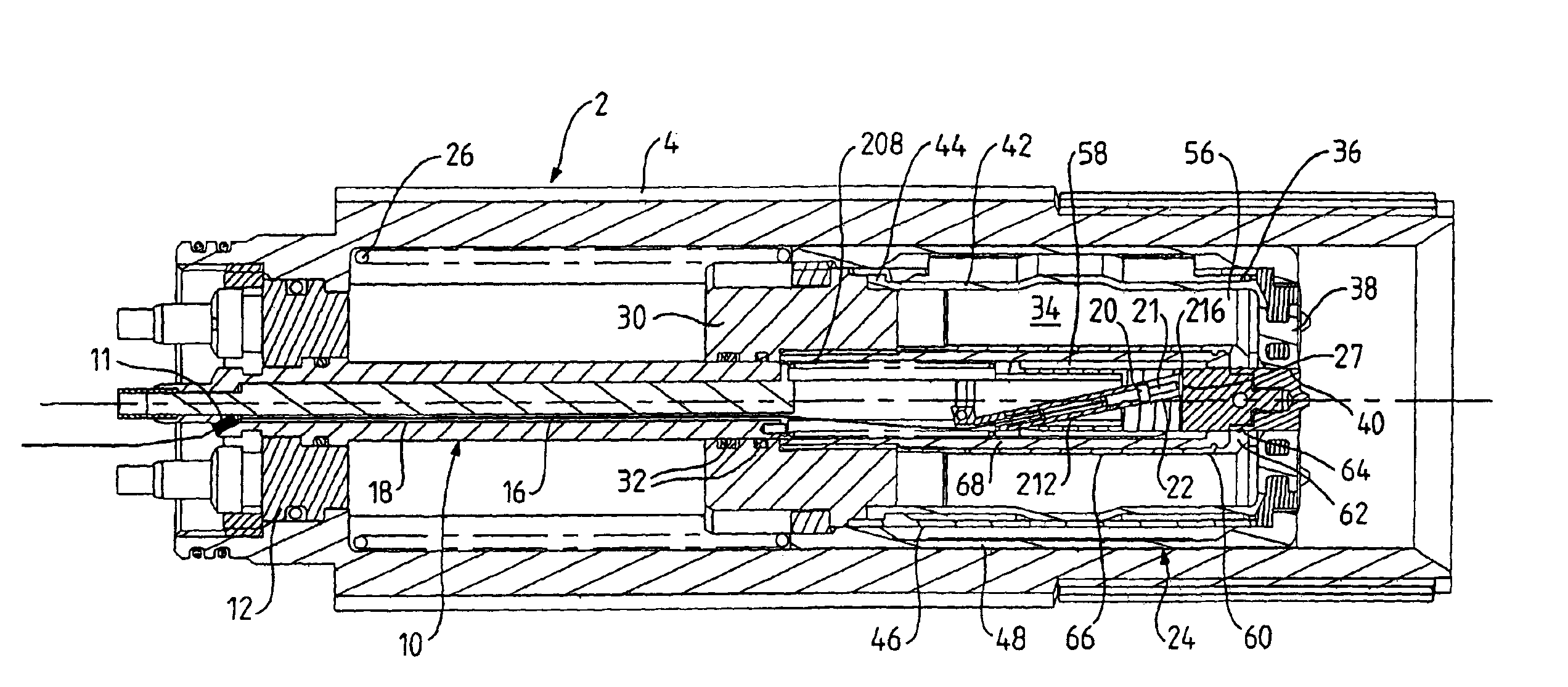
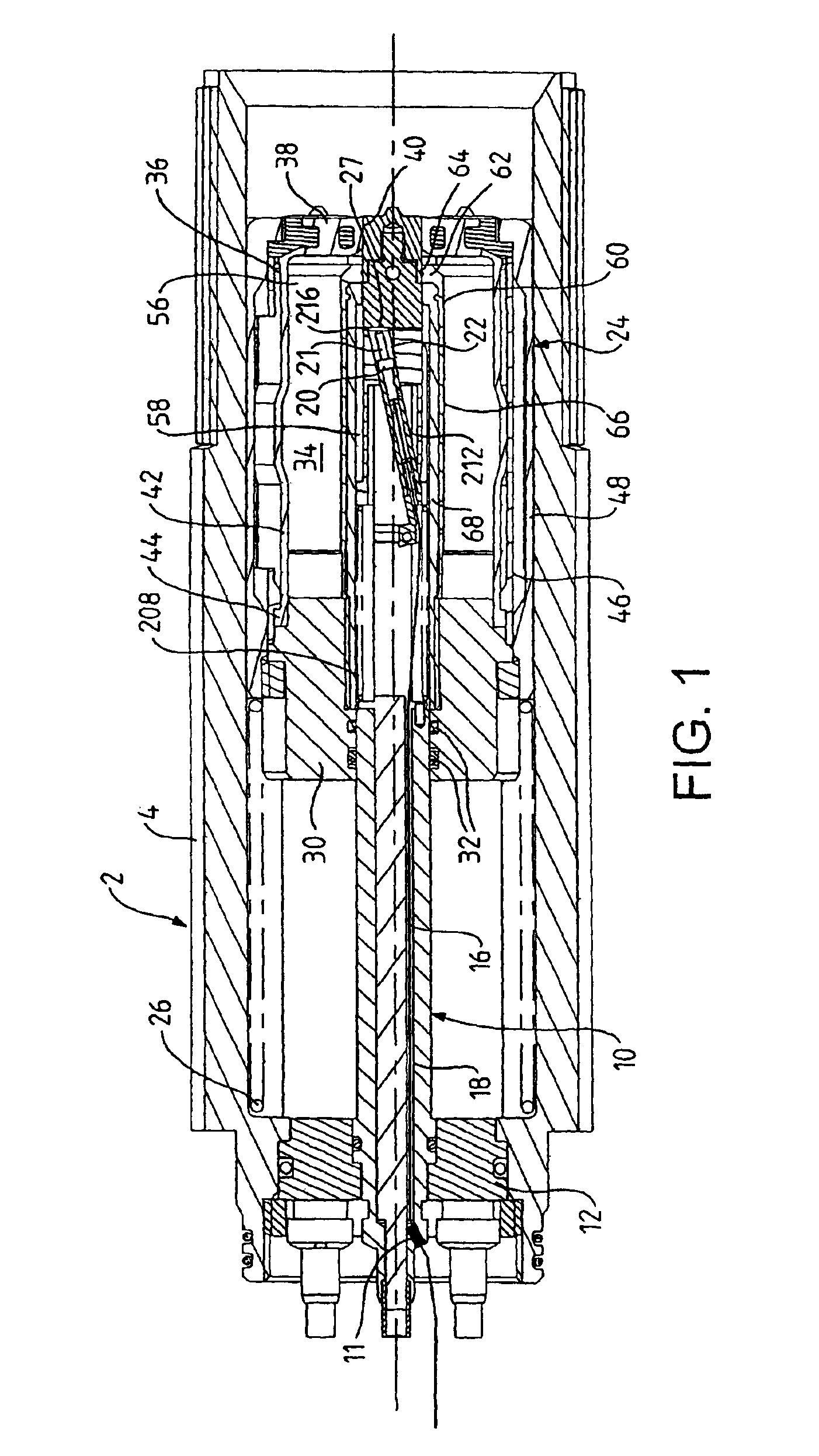
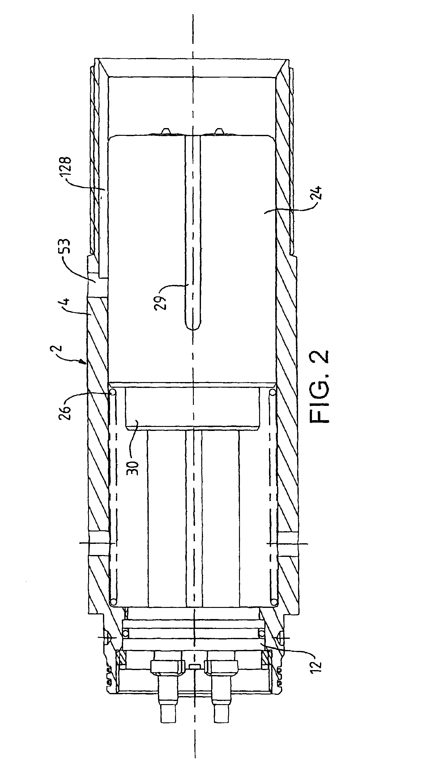
[0064]The embodiment shown in FIGS. 1 to 14 will now be described. FIGS. 1 to 3 show a first connector part 2 having a receptacle 4 for receiving a plug 6 of a second connector part 8, shown in FIGS. 7 to 9. An axially arranged probe 10 projects forwardly from a rear support 12. An optical fibre 16 extends into the probe 10 via a rear opening 11 plugged by an epoxy water block and along a passage 18 in the probe to an optical contact 20 housed in a slanted passage 22 of the probe. At the front end of the optical contact 20, an optical pin 21 is provided. A front opening 27 is provided at the forward end of the slanted passage 22, where a seal 216 is also provided.

[0065]The construction of the probe 10 is best seen in FIGS. 4 to 6 and 15. At its forward end the probe has a nose portion 200. Behind it an electrical probe contact portion 202 is provided. The probe contact portion 202 is supported at the front end of a pair of axially extending conductive arms 204 which extend inside a ...


PUM


Abstract

A connector for making an optical connection underwater or in a wet environment, including first and second connector parts adapted to be interengaged, the first connector part having a probe and the second connector part having a chamber containing fluid media. The probe has a forward portion for entry into the chamber of the second part containing fluid media during interengagement of the connector parts, so that when the connector parts are interengaged the probe provides an optical path between the first connector part and the chamber of the second connector part and passing into the chamber of the second connector part at a slant to the axial direction. The probe slides axially through the opening in sliding engagement with a seal and continues to do so as the forward portion of the probe advances into the chamber containing fluid media.

Description

[0001]This application is the National Stage of International Application No. PCT / GB01 / 04822 filed Oct. 31, 2001, which claims the benefit of Provisional Application No. 60 / 253,263 filed Nov. 27, 2000, and United Kingdom Patent Application No. GB 0026582.7 filed Oct. 31, 2000.BACKGROUND OF THE INVENTION[0002]This invention relates to an optical connector for making an optical connection underwater or in a wet environment.[0003]Optical fibres are frequently used for communication purposes, and it is often necessary to form an optical connection between the ends of such fibres. This generally involves bringing together two connector components each supporting a respective fibre and making end-to-end contact between the fibres. In the case of underwater connectors, it is known to provide the connector components with end sealing arrangements so that the optical fibre ends are protected from the outside environment when the components are in a disconnected state, the end sealing arrange...

Claims


Application Information

Patent Timeline
IPC IPC(8): G02B6/38G02B6/32
CPCG02B6/3816G02B6/3817G02B6/3878G02B6/32G02B6/389
Inventor JONES, MARK R.MCKINNON, GILLIAN A.
Owner SIEMENS ENERGY GLOBAL GMBH & CO KG
Learn More