Fully filled wet clutch with hydrodynamic cooling

a technology of hydrodynamic cooling and fully filled wet clutches, which is applied in the direction of rotary clutches, fluid couplings, gearings, etc., can solve the problems of increasing especially the problem of increasing the problem of torque, and achieving a very large torqu

Inactive Publication Date: 2005-08-16
ZF FRIEDRICHSHAFEN AG
View PDF9 Cites 29 Cited by
  • Summary
  • Abstract
  • Description
  • Claims
  • Application Information

AI Technical Summary

Benefits of technology

[0006]The object of the present invention is to provide a wet clutch arrangement, in particular for a motor vehicle, in which the risk of at least local overheating can be eliminated to the greatest possible extent, even at severe loading.
[0009]Whereas in the wet clutch arrangements known from the prior art heat is removed via the fluid, which flows around the friction surface arrangements, in such a manner that a fluid exchange flow is built up which causes fluid to be continuously introduced into the interior of the housing arrangement and heated fluid to be removed, according to the principles of the present invention a circulation of fluid is built up in the housing arrangement which does not necessarily also require a fluid exchange flow at the same time. The fluid circulating in the circulation in the housing arrangement flows around the friction surface arrangements and can therefore contribute to a significantly better removal of heat. The present invention makes particular use of the fact that fluids of this type have a comparatively large heat storage capacity which is a long way from being exhausted after the fluid has flowed once past the friction surface arrangements. On the contrary, in the case of the clutch arrangement constructed in accordance with the principles of the present invention, the fluid flows repeatedly or a number of times around the friction surface arrangements before it is drawn off from the housing arrangement again in the context of the fluid exchange, which is optionally present in parallel. Therefore, when a pump of comparatively small size is used, by means of which the fluid is fed into the housing arrangement and is drawn off therefrom, a significantly improved removal of the thermal energy from the friction surface arrangements can be obtained by one and the same fluid flowing a number of times around said arrangements before it is exchanged. Of course, in the case of the circulation which is built up according to the invention within the housing arrangement, continuous mixing of the circulating fluid with fluid which has been newly introduced into the housing arrangement and is therefore still relatively cold can take place.
[0012]Furthermore, the construction of the clutch arrangement according to the invention can be kept very simple if it is provided that each friction surface arrangement has at least one friction element, and that the at least one friction element of the first friction surface arrangement is coupled by means of the first friction element to the housing arrangement for rotation together, or / and that the at least one friction element of the second friction surface arrangement is coupled by means of the second friction element to the output element for rotation together. Provision may be made here, for example, for the at least one friction element of the first friction surface arrangement or / and the at least one friction element of the second friction surface arrangement to be coupled to at least one part of the conveying blades of the first conveying element and / or of the second conveying element for rotation together.
[0015]Merging the functionalities of the fluid clutch arrangement, on the one hand, and the friction clutch arrangement, on the other hand, gives rise to an overall clutch arrangement which relieves the load on the friction clutch arrangement by introducing a fluid clutch arrangement at the same time. This relieving of load takes place, firstly, by the fact that a certain part of the driving torque is also transmitted by the circulation of fluid between the pump impeller and the turbine wheel, and takes place, secondly, by the fact that heat is removed to an increased extent from the region of the friction clutch arrangement by the Circulation of fluid, and therefore the friction clutch arrangement can, in principle, be subjected to a greater load.

Problems solved by technology

However, especially when starting up with severe slip in the clutch, i.e., for example, when starting up on a hill, wet clutches of this type are often no longer capable of removing to a sufficient extent the heat produced in the region of the friction surface arrangements bearing frictionally against one another, it thus being possible, at least in local regions, for thermal overloading to occur.
This problem is especially also becoming increasingly greater, since modem motor vehicles are increasingly using driving assemblies, for example turbo diesel assemblies with a common rail system, which, even at a low speed of rotation, can output a very large torque which, when a clutch is engaged, is initially converted completely into friction work and therefore heat.

Method used


Image

  • Fully filled wet clutch with hydrodynamic cooling
  • Fully filled wet clutch with hydrodynamic cooling
  • Fully filled wet clutch with hydrodynamic cooling

Examples


Embodiment Construction

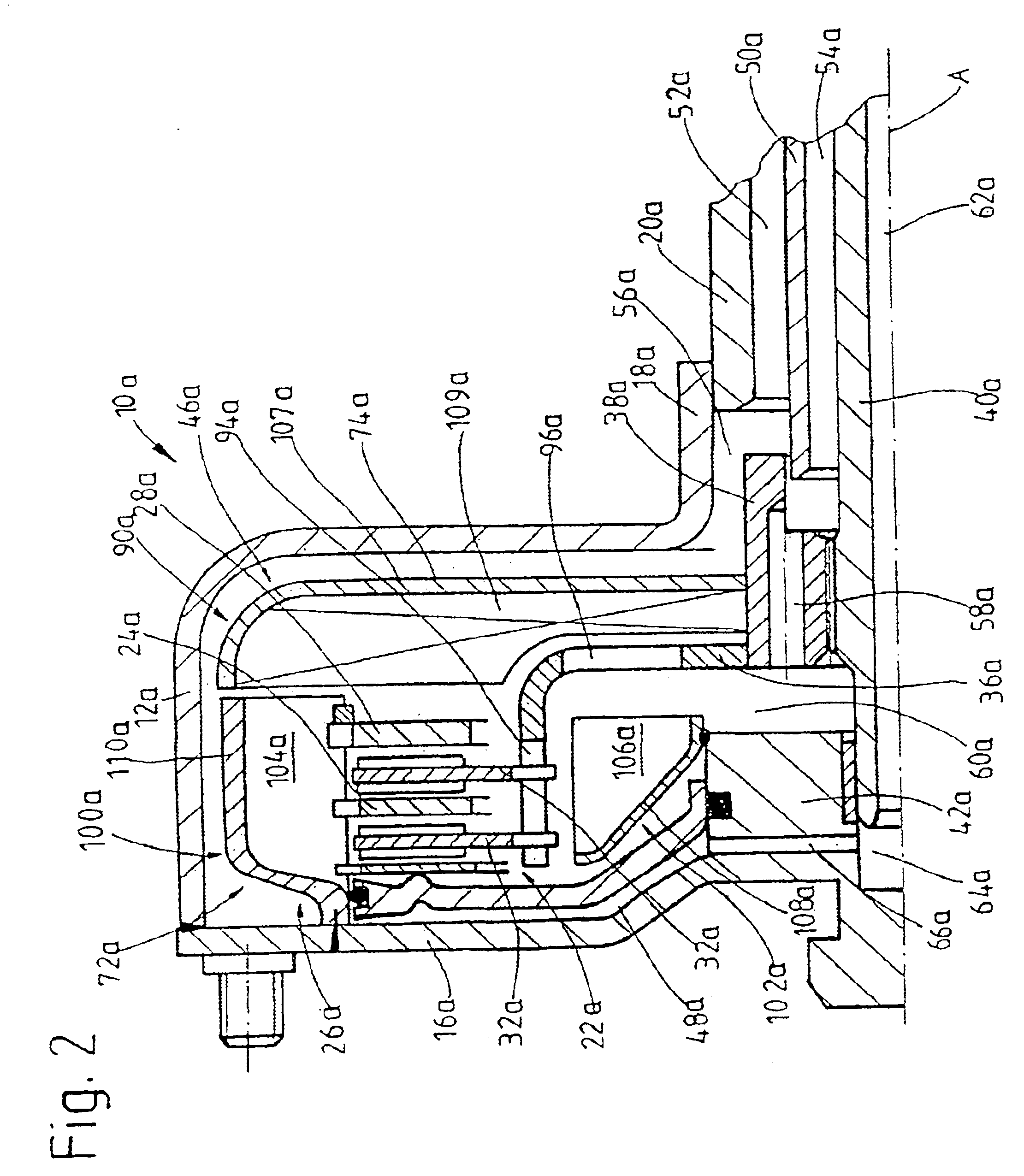
[0021]In FIG. 1, a clutch arrangement 10 includes a housing arrangement with a cup-shaped shell part 14 and a housing cover 16 connected radially on the outside to it. In a manner similar to “hydrodynamic torque converters”, this housing arrangement 12 can be coupled via a flexiplate or the like to a drive shaft of an output assembly, i.e., for example, crankshaft, for rotation together. In a radially inner region, the shell part 14 has a hub region 18 to which a pump drive shaft 20, which is designated as a hollow shaft, is attached.

[0022]The clutch arrangement 10 according to the invention has a friction clutch arrangement 22 in the housing arrangement 12. This friction clutch arrangement 22 comprises a plurality of outer disks 24 which provide respective friction surfaces and are attached via a coupling element 26, for example of ring-like design, to the housing arrangement 12 for rotation together, but, by means of corresponding toothing arrangements, can be displaced with respe...


PUM


Abstract

A fluid clutch includes a housing having an interior that can be filled with fluid, an output element that can be rotated relative to the housing, a first friction surface arrangement coupled to the housing, a second friction surface arrangement coupled to the output element, and means for bringing the first and second friction surface arrangements into frictional engagement. A fluid circulation arrangement in the housing causes fluid to circulate around the friction surfaces without requiring a simultaneous exchange of fluid to and from the interior.

Description

PRIORITY CLAIM[0001]This is a U.S. national stage of application No. PCT / EP01 / 14061, filed on 01 Dec. 2001. Priority is claimed on that application and on the following application: Country: Germany, Application No.: 101 09 497.3, Filed: 28 Feb. 2001.BACKGROUND OF THE INVENTION[0002]1. Field of the Invention[0003]The present invention relates to a clutch arrangement, in particular for a motor vehicle.[0004]2. Description of the Related Art[0005]U.S. Pat. Nos. 6,394,243 and 6,142,180 disclose “wet clutch arrangements” in which various friction surface arrangements are contained in a fluid-filled working space and can be brought into mutual frictional contact by means of a clutch piston, in order to produce a torque transmission connection between a housing arrangement, which is generally coupled to a driving assembly, and an output shaft, i.e. for example, a transmission input shaft. Wet clutch arrangements of this type are used particularly in very heavily stressed regions, since th...

Claims


Application Information

Patent Timeline
Patent Type & Authority Patents(United States)
IPC IPC(8): F16D13/58F16D13/72F16H45/02F16D25/12
CPCF16D13/72F16D25/0638F16D25/123
Inventor SASSE, CHRISTOPH
Owner ZF FRIEDRICHSHAFEN AG
Why Eureka
Try Eureka