Computer system bus interface and control method therefor

Inactive Publication Date: 2005-08-09
IBM CORP
View PDF8 Cites 2 Cited by
  • Summary
  • Abstract
  • Description
  • Claims
  • Application Information

AI Technical Summary

Benefits of technology

[0006]It is, therefore, an object of the present invention to prevent a failure...

Problems solved by technology

This causes the contending device to be maintained in the reset state even if, for exa...

Method used


Image

  • Computer system bus interface and control method therefor
  • Computer system bus interface and control method therefor
  • Computer system bus interface and control method therefor

Examples


Embodiment Construction

[0015]The preferred embodiments of the present invention will now be described in detail with reference to the accompanying drawings. It should be noted, however, that the present invention can be variously modified, and should not limited to the embodiments. The same reference numerals are used throughout the description of the embodiments to denote corresponding or identical components.

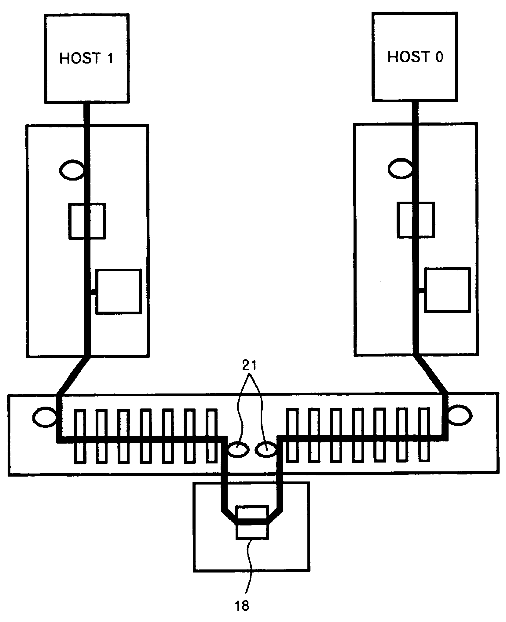
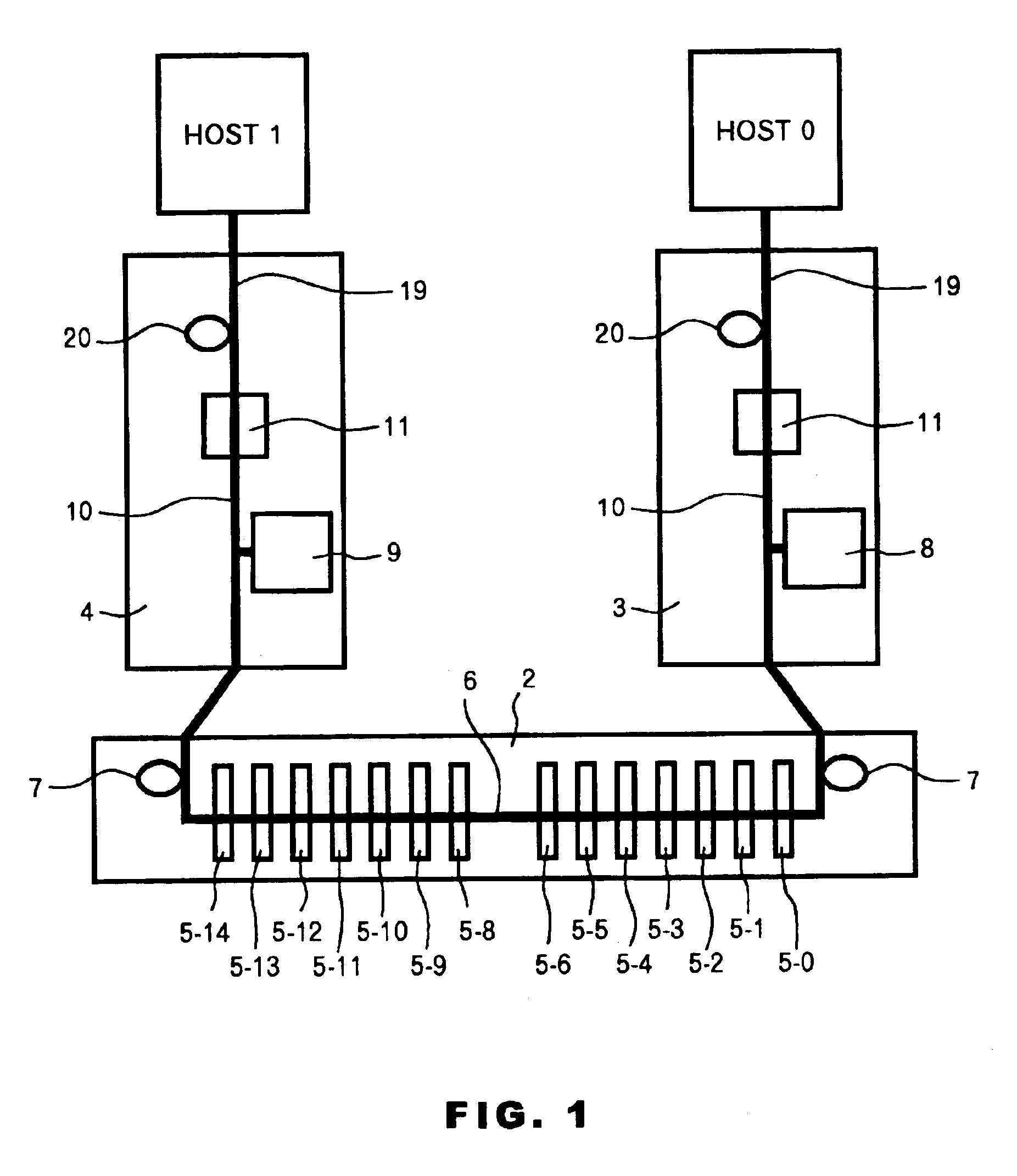
[0016]FIG. 1 is a block diagram illustrating an example of a computer system according to the embodiment of the present invention. The computer system in this embodiment comprises a host computer Host0, a host computer Host1, an enclosure 2, and interface cards 3 and 4.

[0017]The first host computer Host0 has a device ID of, for example, #7 and is connected to a SCSI bus of the enclosure 2 via the interface card 3. The second host computer Host1 has a device ID of, for example, #6 and is connected to the SCSI bus of the enclosure 2 via the interface card 4. Although the device ID (#7) having the high...


PUM


Abstract

When a device ID of a second, or subsequent, host computer contends with a device ID of another device that can be connected to a SCSI bus, a reset signal (RST) is applied to a SCSI control bus input of the contending device. The contention is determined by detecting whether a terminal power of the second, or subsequent, host computer is active.

Description

FIELD OF THE INVENTION[0001]The present invention relates to a computer system with SCSI (Small Computer System Interface), a bus interface and a control method therefor, and in particular to an effective technique for use in bus control when a contention of SCSI device IDs occurs.BACKGROUND ART[0002]SCSI (Small Computer System Interface) is a well-known standard I / O bus. Standards have been established for bus widths of 8 bits and 16 bits that provide a maximum data transfer rate of 160 MB / sec. According to the standard for the 8 bit bus width, up to eight device IDs (#0 to #7) can be assigned while, according to the standard for the 16 bit bus width, up to 16 device IDs (#0 to #15) can be assigned. A host computer must also be assigned a device ID, which is typically #7. A variety of devices, including hard disk drives, CD-ROMs and scanners, can be connected to a SCSI bus.[0003]Because of a demand for high extensibility in a computing system, there has been a great demand for conn...

Claims


Application Information

Patent Timeline
IPC IPC(8): G06F13/40G06F13/14
CPCG06F13/4086
Inventor SAKABA, SHIGEONOJIMA, KATSUYUKI
Owner IBM CORP
Why Eureka
Try Eureka