Ultrasonic current meter

Inactive Publication Date: 2005-08-09
TOKIMEC INC
View PDF9 Cites 11 Cited by
  • Summary
  • Abstract
  • Description
  • Claims
  • Application Information

AI Technical Summary

Benefits of technology

[0009]Since the present invention obtains the flow velocity from a phase difference, it needs only a low voltage burst signal compared to the conventional propagation time difference type, requires no power supply circuit to generate a high voltage, requires no counter circuit which needs to operate at high speed, and can thereby reduce the size and power consumption of the apparatus and improve its explosion proof characteristic. Furthermore, since the present invention uses a burst signal, it is possible to allow the pair of transmission / reception ultrasonic transducers to perform transmission and reception simultaneously, reduce the number of parts and realize a small and low-cost configuration. Furthermore, the use of a burst signal allows processing for a phase difference measurement and flow velocity measurement after transmission and reception to be carried out intermittently, making it possible to realize the apparatus with low power consumption unlike the conventional one which processes continuous waves all the time. It will be easily understood that the present invention is not limited to the use of only a pair of transmission / reception ultrasonic transducers and the present invention can be adapted to have a plurality of pairs of transmission / reception ultrasonic transducers to reduce influences of measurement errors due to deviation of a flow velocity distribution and improve the accuracy. In this case, this adaptation is made by carrying out measurements by switching between the pairs of transmission / reception ultrasonic transducers or providing a plurality of lines of some measurement circuits.
[0020]The low power ultrasonic flow velocity meter can be connected to a power supply through a two-wire loop and further can comprise a two-wire interface section for transmitting measured values obtained by the flow velocity measuring means using the two-wire loop. The two-wire loop alone can supply a supply voltage and send the measurement result. The ultrasonic flow velocity meter of the present invention is designed to reduce power consumption, and can thereby be operated with even a low supply voltage from such a two-wire loop satisfactorily.

Problems solved by technology

This requires a power supply circuit to generate a high voltage in the apparatus, which constitutes a great obstacle in downsizing of the apparatus and reduction of power consumption.
Furthermore, application of a high-voltage signal to the ultrasonic transducer limits its use in a place full of explosive gas.
Furthermore, an accurate measurement of an ultrasonic propagation time requires the use of a counter with a high count frequency, which increases power consumption and also constitutes a great obstacle against low power consumption in this sense.
However, when used for such continuous waves, transmission ultrasonic transducers and reception ultrasonic transducers, at least two each, four in total are required, resulting in problems that the cost increases as the number of parts increases and the size of the apparatus increases and that consecutive transmissions and receptions will also increase power consumption.

Method used


Image

  • Ultrasonic current meter
  • Ultrasonic current meter
  • Ultrasonic current meter

Examples


Embodiment Construction

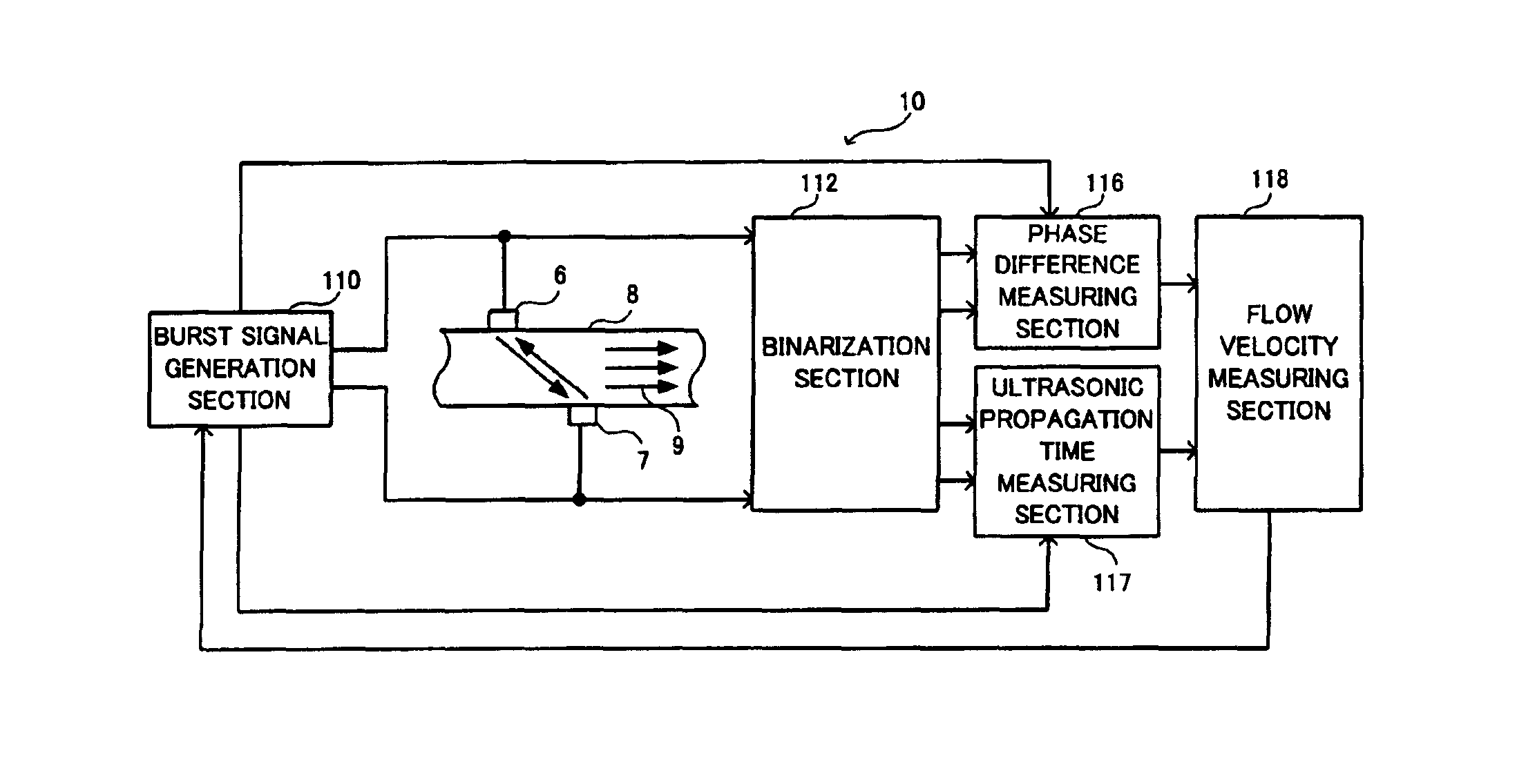
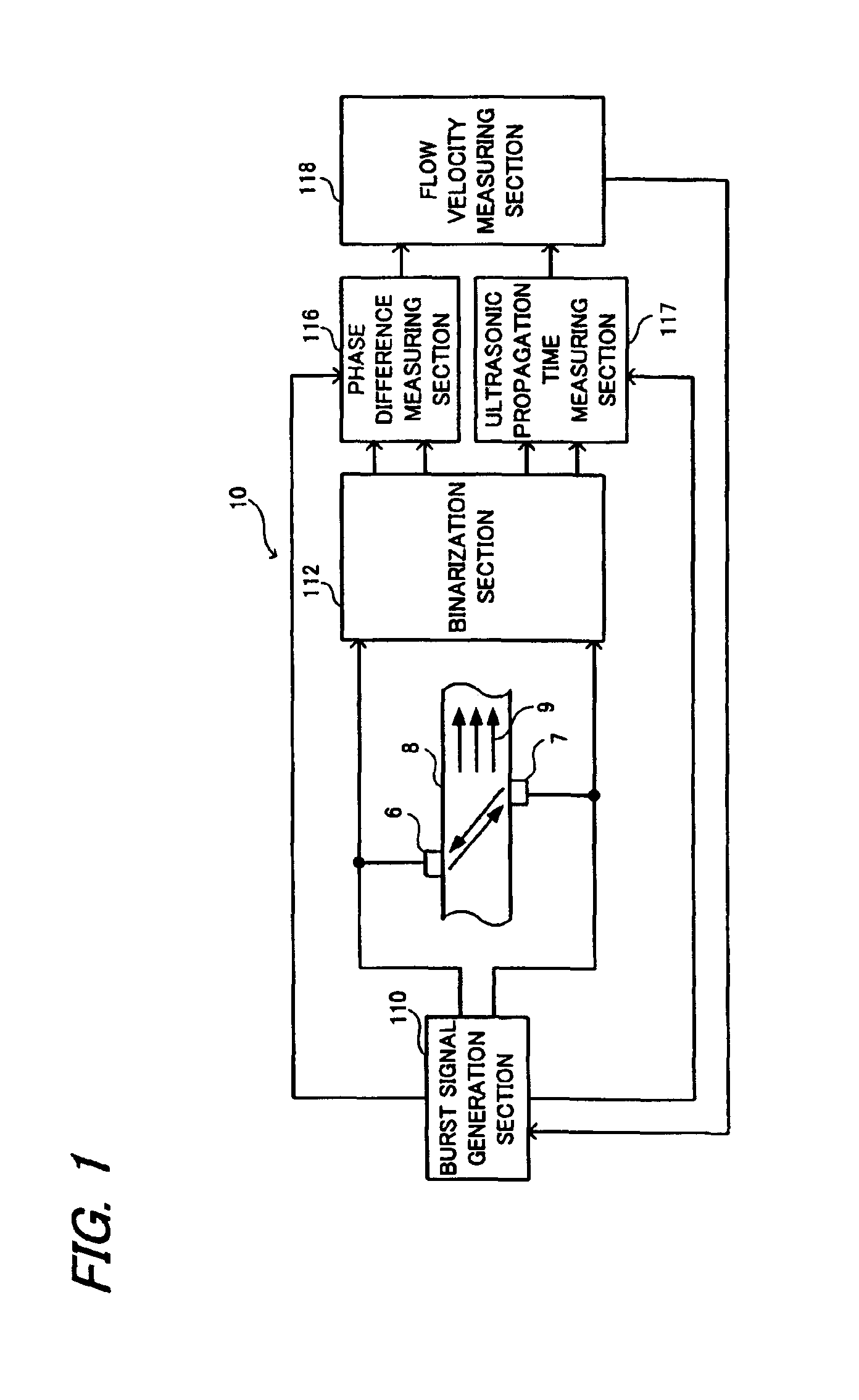
[0044]With reference now to the attached drawings, embodiments of the present invention will be explained below. FIG. 1 is a block diagram of an ultrasonic flow velocity meter according to the present invention.

[0045]In the figure, an ultrasonic flow velocity meter 10 generally includes a burst signal generation section 110 which generates two kinds of burst signals having a phase difference, a pair of transmission / reception ultrasonic transducers 6 and 7, a binarization section 112 which binarizes the received signals from the transmission / reception ultrasonic transducers 6 and 7, a phase difference measuring section 116 which calculates a phase difference between the respective binarized received signals, an ultrasonic propagation time measuring section 117 and a flow velocity measuring section 118 which measures the flow velocity and flow rate of a conduit to be measured based on a phase difference signal from the phase difference measuring section 116. The pair of transmission / r...


PUM


Abstract

The present invention provides a small, low power consumption ultrasonic flow velocity meter. The burst signal generation section 110 generates two kinds of burst signals with a phase difference and sends these burst signals to a pair of transmission / reception ultrasonic transducers 6 and 7 located on the upstream side and downstream side of the conduit to be measured 9. Upon reception of the corresponding burst signals, the pair of the transmission / reception ultrasonic transducers 6 and 7 convert the burst signals, send ultrasonic waves with a phase difference to the conduit to be measured 9, receive the ultrasonic wave sent by the other transmission / reception ultrasonic transducer and propagated through the conduit to be measured and convert the ultrasonic waves to received signals. These received signals are binarized through the binarization circuits 16 and 17, exclusive-ORed by the exclusive-OR circuit 30 and converted to a phase difference signal indicating a phase difference and the flow velocity of the conduit to be measured 9 is measured based on this phase difference signal.

Description

TECHNICAL FIELD[0001]The present invention relates to an ultrasonic flow velocity meter which measures a flow velocity of a fluid based on a time difference in propagation of an ultrasonic wave.BACKGROUND ART[0002]As an example of a conventional ultrasonic flowmeter using an ultrasonic flow velocity meter of this type, an ultrasonic flowmeter based on a propagation time difference is known. In such a current meter, an ultrasonic transducer is placed on the upstream side and downstream side of a conduit to be measured respectively and uses an impulse signal or step signal as a transmission signal, sends out ultrasonic waves from two ultrasonic transducers on the upstream side and downstream side alternately and measures the time difference in propagation of the received signal using a high-speed counter circuit.[0003]However, such an ultrasonic flowmeter based on a propagation time difference is required to have a high signal-to-noise ratio to accurately determine the propagation tim...

Claims


Application Information

Patent Timeline
IPC IPC(8): G01F1/66G01P5/24G01P5/00
CPCG01F1/667G01P5/245
Inventor KISHIMOTO, MASAOMOTEGI, RYOHEISUZUKI, YUKIHIKOIWABUCHI, HIROSHI
Owner TOKIMEC INC
Why Eureka
Try Eureka