Tool for machining workpieces

a technology for workpieces and tools, applied in the direction of manufacturing tools, saw blades, metal sawing accessories, etc., can solve the problems of not being able to realize an exact setting, not being able to finely adjust the cone, and being able to achieve an exact setting only at an increased production cos

Inactive Publication Date: 2005-08-09
MAPAL
View PDF8 Cites 13 Cited by
  • Summary
  • Abstract
  • Description
  • Claims
  • Application Information

AI Technical Summary

Benefits of technology

[0009]The parent body of the tool preferably has an abutment which prevents a displacement of the setting element in the direction along the center axis and on which the setting element is supported when the adjusting device is actuated. The abutment advantageously comprises a welded connection between the setting element and the parent body.
[0012]According to embodiments of the invention, the radial distance of the cutting edge may be either increased or reduced by the setting element. In other embodiments, the setting element may only be operable to reduce the radial distance. A single same setting element may serve both to increase and reduce the radial distance of the cutting edge.

Problems solved by technology

There are high frictional forces between the surface and the cone, so that fine adjustment of the cone is often not possible.
As a result, it is often not possible to realize an exact setting, or it is possible only at an increased production cost.
It has also been found that a displacement of the cutting edge is not reversible in many cases.

Method used


Image

  • Tool for machining workpieces
  • Tool for machining workpieces
  • Tool for machining workpieces

Examples


Embodiment Construction

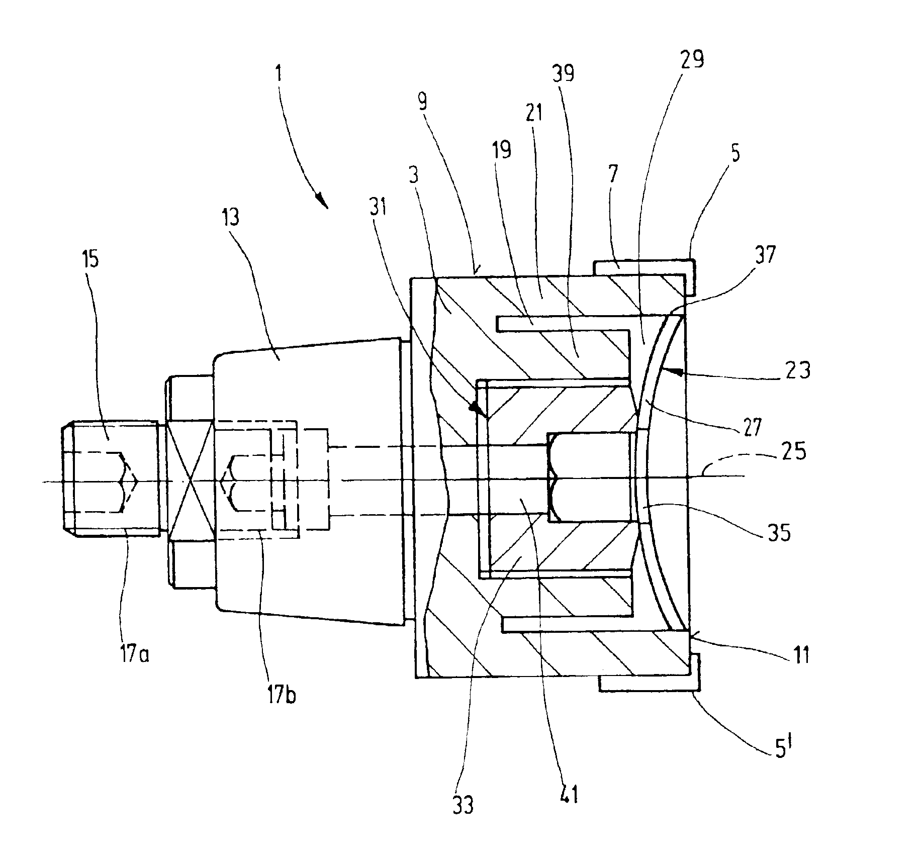
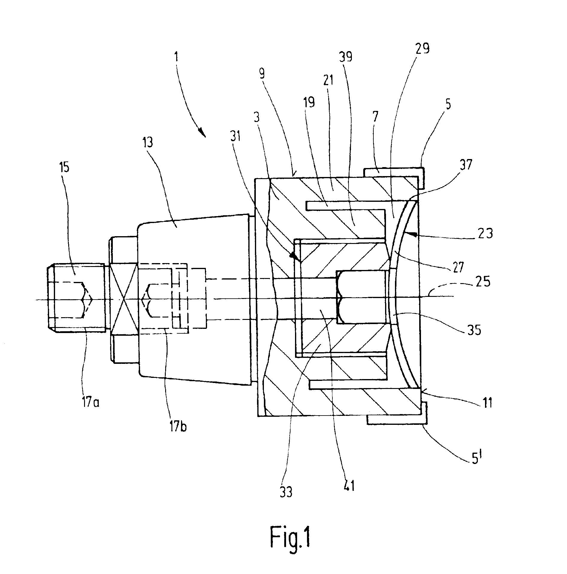
[0023]FIG. 1 shows a tool 1 for machining workpieces, having a parent body 3 which is provided with at least one geometrically defined cutting edge 5, for removing chips from a workpiece. The cutting edge 5 may be part of the parent body 3. In the exemplary embodiment shown here, the cutting edge 5 is part of a cutting tip 7 which is inserted into the parent body 3. The fastening of cutting tips 7 to a parent body 3 of a tool 1 is known. As a rule, the cutting tips 7 are inserted into a groove, so that they are securely held and the forces produced during the machining of workpieces are directed into the parent body 3. The cutting tips can be brazed in place in the parent body 3 or can be clamped in place therein by means of known clamping shoes. Finally, it is also possible to fasten the cutting tips to the parent body 3 directly with a screw or thread.

[0024]Two opposite cutting edges 5 and 5′ are shown in FIG. 1. It is possible to provide more than two cutting edges on the parent ...


PUM

PropertyMeasurementUnit
opening angleaaaaaaaaaa
radial distanceaaaaaaaaaa

Abstract

A tool for machining workpieces, having a parent body which can be expanded at least zonally, having at least one geometrically defined cutting edge projecting beyond a circumferential surface of the tool, and having a setting device influencing the radial distance of the cutting edge from the center axis of the tool. The setting device has a setting element, and an adjusting device which sets the degree of bending of the setting element. The setting element is inserted into the parent body of the tool in such a way that, when the bending of the setting element is varied, the radial distance of the cutting edge is varied.

Description

BACKGROUND OF THE INVENTION[0001]1. Field of the Invention[0002]The invention relates to a tool for machining workpieces having a parent body which can be expanded at least in selected zones thereof, having at least one geometrically defined outer cutting edge projecting beyond a circumferential surface of the tool, and having a setting device that sets the radial distance of the cutting edge from the center axis of the tool.[0003]2. Related Art[0004]Tools of this type are known. They serve to remove chips from a workpiece by means of a cutting edge, for example during the surface machining of bores. As a rule, the tool is set in rotation in order to produce a relative movement between the cutting edge and the workpiece surface to be machined and in order to remove chips. However, it is also possible to set the workpiece in rotation and to clamp the tool in a rotationally fixed position.[0005]Tools which have a setting device, by means of which the position of the circumferential cu...

Claims


Application Information

Patent Timeline
Patent Type & Authority Patents(United States)
IPC IPC(8): B23D77/00B23D77/10B23C5/22B23C5/06
CPCB23D77/10B23B2260/136Y10T408/85843Y10T408/85892Y10T408/858Y10T83/9326Y10T83/9321Y10T83/9346Y10T83/9377
Inventor KRESS, DIETERHABERLE, FRIEDRICH
Owner MAPAL
Why Eureka
Try Eureka