
Thermal generator for downhole tools and methods of igniting and assembly

a generator and downhole tool technology, applied in the direction of ammunition fuzes, lighting and heating apparatus, borehole/well accessories, etc., can solve the problems of inconsistency, accidental detonation, black powder performance inconsistently, etc., and achieve the effect of improving the reliability of the downhole tool

Inactive Publication Date: 2005-08-09
ROBERTSON MICHAEL C
View PDF16 Cites 91 Cited by
  • Summary
  • Abstract
  • Description
  • Claims
  • Application Information

AI Technical Summary

Benefits of technology

[0009]It is a further object of the present invention to provide an ignition device for a downhole tool that performs reliably.

Problems solved by technology

The prior art detonators present safety concerns in that accidental detonation can occur.
Furthermore, black powder performs inconsistently, depending upon various factors such as downhole conditions and even assembly of the detonator and loading the detonator into the tool.
Such inconsistency adversely affects the reliability of the downhole tool.

Method used


Image

  • Thermal generator for downhole tools and methods of igniting and assembly
  • Thermal generator for downhole tools and methods of igniting and assembly
  • Thermal generator for downhole tools and methods of igniting and assembly

Examples


Embodiment Construction

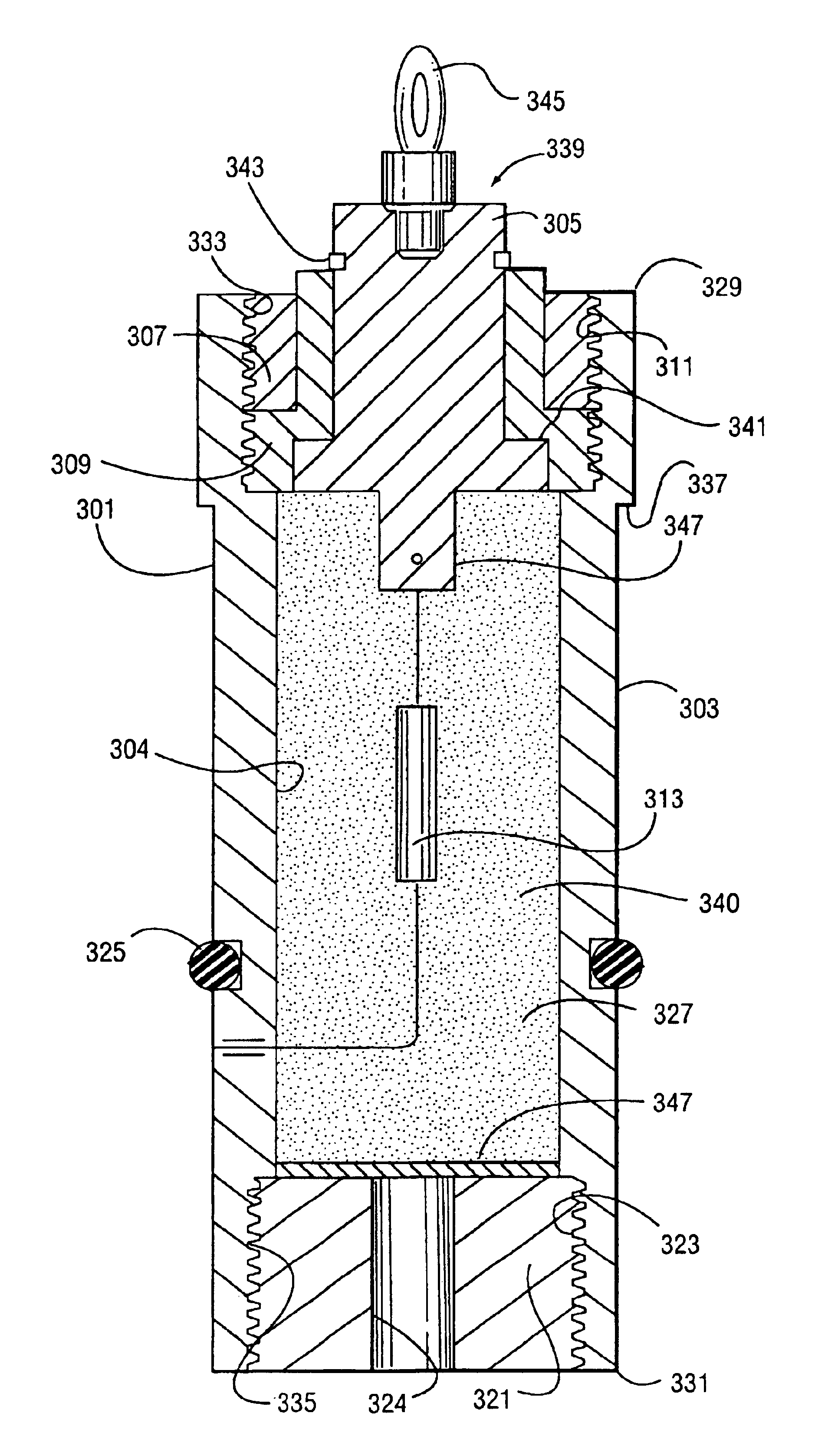
[0037]The present invention provides a thermal generator (FIG. 11) for use in a variety of applications, and typically in conjunction with downhole tools in oil and gas wells. The thermal generator is an electrically operated initiator. As such, the thermal generator initiates an exothermic reaction, which propagates heat to an adjacent ignitable material. The secondary material, when ignited, produces the desired high temperature and energy release.

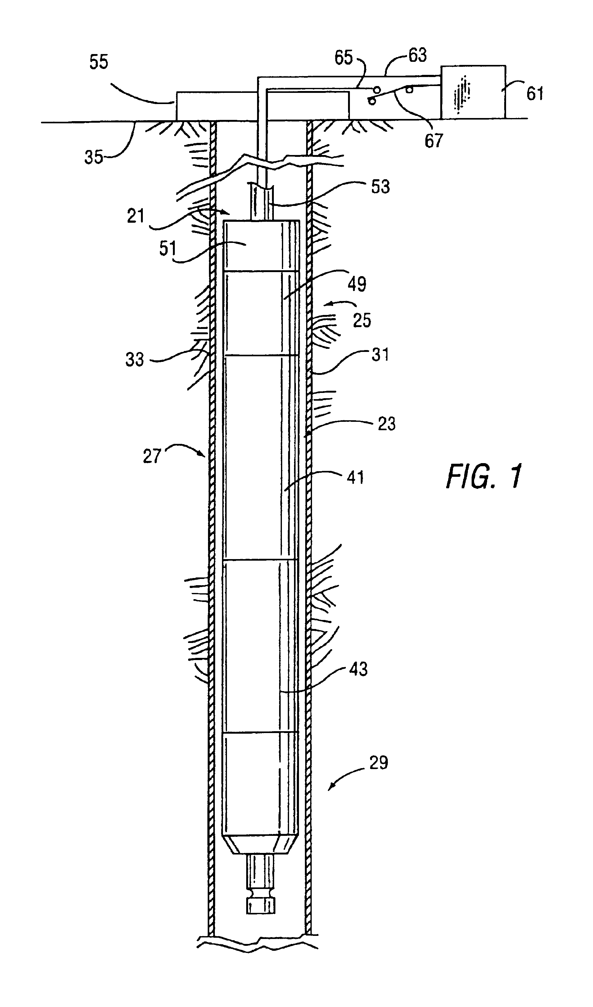
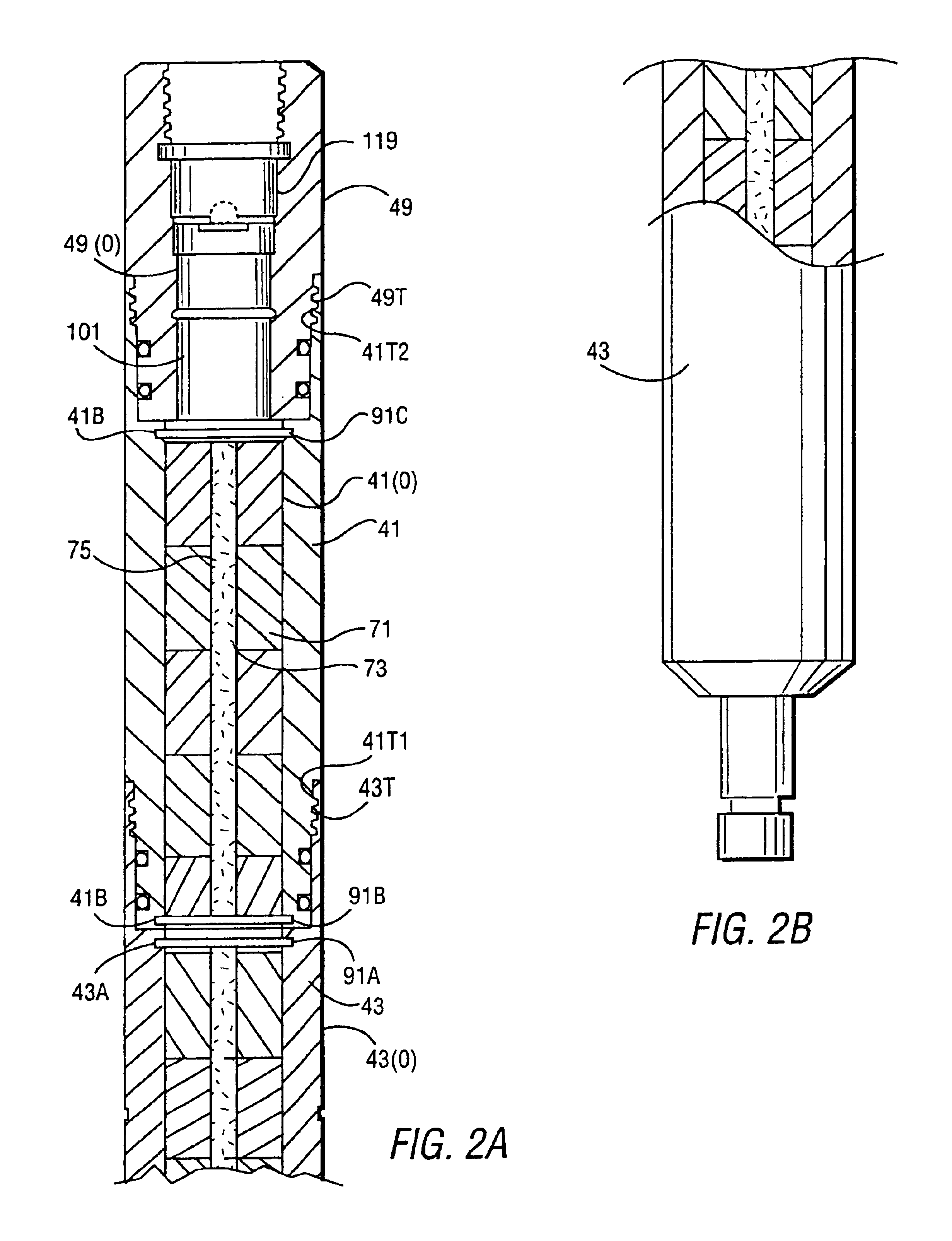
[0038]In the description that follows, the thermal generator is described in the context of a radial cutting torch. The thermal generator can also be used in conjunction with setting tools, perforating tools and jet cutters.

[0039]The thermal generator of FIG. 11 is used with a conductive wire line. Thus, the initiation current is provided from the surface.

[0040]The thermal generator is safe in that the risk of accidental initiation is very low. A flammable material having a high ignition temperature is utilized. Consequently, the energy ...


PUM


Abstract

An ignition device for a downhole tool includes a body with a cavity, a thermite material and a resistive element within the cavity. The resistive element, which is heated to the high temperature needed for ignition of the thermite material, has a non-galvanic outer surface at the ignition temperature. A large amount of electrical power is required to reach the ignition temperature, making the device safe and unlikely to accidentally ignite. The device has an electrical connector that is located within a sealed chamber when downhole.

Description

[0001]This application is a continuation-in-Part application of Ser. No. 09 / 955,686, filed Sep. 19, 2001 now U.S. Pat. No. 6,598,679.FIELD OF THE INVENTION[0002]The present invention relates to ignition devices for downhole tools, such as cutting torches, setting tools, perforating tools, jet cutters, and the like.BACKGROUND OF THE INVENTION[0003]When completing an oil or gas well, there is a frequent need to penetrate or cut casing or pipe in the borehole. For example, a length of casing may be stuck in the hole, preventing retrieval. To retrieve, or salvage, the casing, a cutting tool is lowered downhole. The cutting tool contains flammable materials that are ignited and produces a flame that cuts the surrounding casing.[0004]The initial ignition of the flammable materials is caused by an electrical initiator. The role of the initiator is to safely ignite only when intended, so as to prevent accidental, or premature, ignition, and to reliably ignite once the tool is downhole and p...

Claims


Application Information

Patent Timeline
Patent Type & Authority Patents(United States)
IPC IPC(8): E21B29/00E21B29/02
CPCE21B29/02
Inventor ROBERTSON, MICHAEL C.
Owner ROBERTSON MICHAEL C
Learn More