
Method and device for calibrating rotary axis

Inactive Publication Date: 2005-08-09
FIVES MACHINING SYST +1
View PDF1 Cites 16 Cited by
  • Summary
  • Abstract
  • Description
  • Claims
  • Application Information

AI Technical Summary

Benefits of technology

[0013]The present invention is for a device and a method for measuring and calibrating the rotary motion of a rotatable machine member, such as a pivotable swivel member of a spindle of a five-axis machine tool. The device includes an arm mounted to the spindle, a housing mounted to the arm, an optical encoder mounted internal to the arm and positioned therein to measure rotation about an axis extending lengthwise along the housing, which such axis is parallel to the axis about which the swivel member rotates. The device also includes a rotary table mounted to the housing opposite

Problems solved by technology

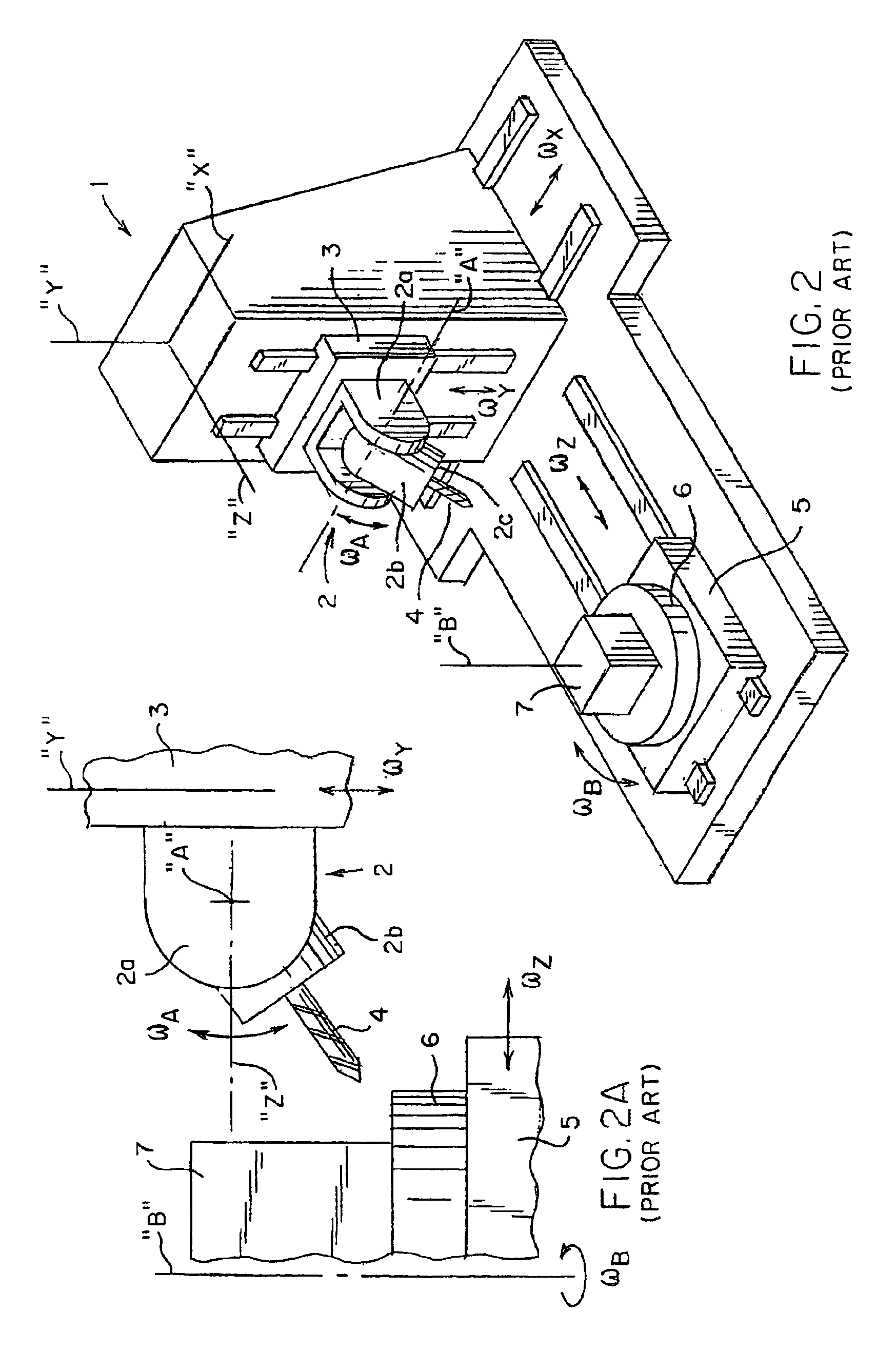
Tool 4, then, may approach the workpiece 7 at many angles oblique thereto, thereby increasing the complexity of the machining operations which may be performed by the machine tool 1.
However, because this method requires manual positioning of the level, any error compensation values obtained thereby may include unavoidably inaccuracies.

Method used


Image

  • Method and device for calibrating rotary axis
  • Method and device for calibrating rotary axis
  • Method and device for calibrating rotary axis

Examples


Embodiment Construction

[0037]With reference to FIG. 3, a rotary calibration device 100 according to one embodiment of the present invention is removably affixable to a machine member, for example, a swivel member 2b of a spindle 2 of a five axis machine tool 1. Although the device 100 will be described herein with reference to a swivel member 2b of a spindle 2 of a five-axis machine tool 1, it will be apparent to those of ordinary skill in the art, upon reading the within detailed description, that the present invention may be affixed to any rotatable machine member for calibration of the rotary motion thereof. For example, machines such as composite tape-laying or fiber-placement machines, which typically provide multiple axes of rotary movement, may utilize the device and method hereof to calibrate motion of each such axis.

[0038]More particularly, and with additional reference now to FIGS. 4 and 5, the device 100 includes a rigid arm 110 having a base plate 112 and a fixture 114 secured to the base plat...


PUM


Abstract

A present invention is for a device and method for measuring and calibrating the rotary motion of a rotatable machine member, such as a pivotable swivel member (2b) of a spindle (2) of a five-axis machine tool (1). The device includes an arm (110) mounted to the spindle, a housing (120) mounted to the arm, an optical encoder mounted internal to the arm and positioned therein to measure rotation about an axis extending lengthwise along the housing, which such axis is parallel to the axis about which the swivel member rotates. The device also includes a rotary table (170) mounted to the housing opposite the arm, the rotary table comprising a stator (171) fixedly mounted to the housing and a rotor (172) clampedly affixed to a shaft passing through the housing. The shaft is coupled to an input shaft of the encoder such that rotary movement of the rotor can be measured by the encoder. An electronic level (190) fixedly secured to the rotor, such as by a bracket (180). The encoder, the rotary table and the level are each electronically coupled to a control system which is adapted to obtain readings from the encoder and from the level and to command controlled rotation of the rotor relative to the stator.

Description

[0001]This application claims the benefit of Provisional Application No. 60 / 208,152, filed May 31, 2000.BACKGROUND OF THE INVENTION[0002]The present invention relates to methods and devices for measuring and calibrating angular positioning of a machine member about a rotary axis. More particularly, the present invention relates to methods and devices for measuring and calibrating angular positioning of a machine member about a rotary axis, wherein a compensation value is empirically derived for each of one or more commanded rotary positions, and wherein the compensation value is based upon an actual rotary position accurately measured for a given commanded rotary position.[0003]With reference to FIG. 1, a conventional machine tool 1, for example, a horizontal machining center, typically includes a spindle 2 mounted in a spindle carrier 3 for high-speed rotation about an axis parallel to a spindle axis “Z”. The spindle carrier 3 is typically translatable in directions ωX, ωY parallel...

Claims


Application Information

Patent Timeline
IPC IPC(8): B23Q1/25B23Q17/22B23Q1/54G05B19/401G01B21/24
CPCB23Q1/5406B23Q17/2233G01B21/24G05B19/401G05B2219/37376G05B2219/50027G05B2219/50132
Inventor COMER, PAULPURTELL, DAVIDSHIVASWAMY, SATISH
Owner FIVES MACHINING SYST
Learn More