
Compact structure for automatically filling solid pharmaceutical product packages

a technology of automatic packaging and pharmaceutical products, applied in the direction of packaging goods, liquid handling, transportation and packaging, etc., can solve the problems of unsatisfactory existing machinery, less space available for a substantial amount of machinery, and more difficult to achieve horizontal displacement of products into desired locations, etc., to achieve high-speed operation and ease of operation. the effect of the user

Inactive Publication Date: 2005-08-09
MTS MEDICATION TECH INC
View PDF3 Cites 62 Cited by
  • Summary
  • Abstract
  • Description
  • Claims
  • Application Information

AI Technical Summary

Benefits of technology

[0008]One object and advantage of the present invention is to provide a solid pharmaceutical product packaging machine that is capable of providing a wide variety of solid pharmaceutical sources. Another object and advantage of the present invention is to provide a solid pharmaceutical product packaging machine that is more efficient in terms of its physical size than devices of the prior art. Other objects and advantages will be apparent in light of the following Summary and detailed Description of the Presently Preferred Embodiments.
[0009]In accordance with a preferred exemplary embodiment of the present invention, a solid pharmaceutical product packaging machine automatically fills blister package cavities with one or more individual doses of one or more solid pharmaceutical products. Advantageously, the cavity dispensing cabinet may be a significant height and almost as high as the height of a typical room which usually has eight foot ceilings. The cabinet is sized in this manner so that a larger variety solid pharmaceutical products may be accommodated in individual automated dispensing cam canisters contained within the cabinet or dispensing portion. In a particularly preferred exemplary embodiment, the cabinet member may be modularly expandable depending upon the particular needs of the facility using this machine.
[0010]The individual dispensing canisters are preferably controlled by a computer, such as, for example, a personal computer that is programmed to selectively dispense solid pharmaceutical products according to a patient prescription. In accordance with the preferred embodiment, solid pharmaceutical products are selectively ejected from the individual canisters and are directed into a funnel that transmits the individual solid pharmaceutical products into select cavities of a temporary storage member. Advantageously, this temporary storage member is located in a structure that is capable of selectively manipulating the position of the individual cavities of the temporary storage member beneath the funnel. This enables the device to selectively dispense one or more solid pharmaceutical products into a given cavity of the temporary storage member.
[0011]Conventional designs of similar systems which rely upon the canister dispensing technology described herein are exemplified by co-pending U.S. patent application Ser. No. 09 / 704,134 titled Automated Solid Pharmaceutical Product Packaging Machine filed on Nov. 1, 2000 and Ser. No. 09 / 539,834 titled Automated Solid Pharmaceutical Product Packaging Machine filed Mar. 31, 2000. Each of these co-pending United States patent applications are incorporated herein by reference.
[0012]In accordance with a preferred exemplary embodiment, the structure that is capable of selectively manipulating the position of the temporary storage member is located very near to the floor of the facility within which the system is operated. This desirably enables a substantial number of solid pharmaceutical products to be dispensed by the device. Subsequent operational aspects of the machine ensure that the physical location of the temporary storage member is not a hindrance to the overall performance characteristics of the machine and the ease with which it may be operated by a user.
[0013]In accordance with the preferred exemplary embodiment, once the temporary storage member has been filled with the desired number of solid pharmaceutical products by the dispensing apparatus, the solid pharmaceutical members are transferred into a further temporary storage member that traverses in the horizontal directions away from the initial temporary storage member. This enables high-speed operation of the device because the system may be used to selectively fill another patient prescription while the initial prescription is being further processed by the system.

Problems solved by technology

Consequently it is more difficult to achieve horizontal displacement of the products into a desired location.
As a result, the machines for dispensing the products and filling the blister packages may be placed at a level that is undesirable because it is preferable to have the canisters physically located above the location into which the solid pharmaceutical products are dropped.
Hospitals and / or other managed care facilities that typically utilize these devices do not usually have a substantial amount of additional space available for the machinery.
Consequently, in light of these concerns and requirements, the existing machinery has been unsatisfactory.

Method used


Image

  • Compact structure for automatically filling solid pharmaceutical product packages
  • Compact structure for automatically filling solid pharmaceutical product packages
  • Compact structure for automatically filling solid pharmaceutical product packages

Examples


Embodiment Construction

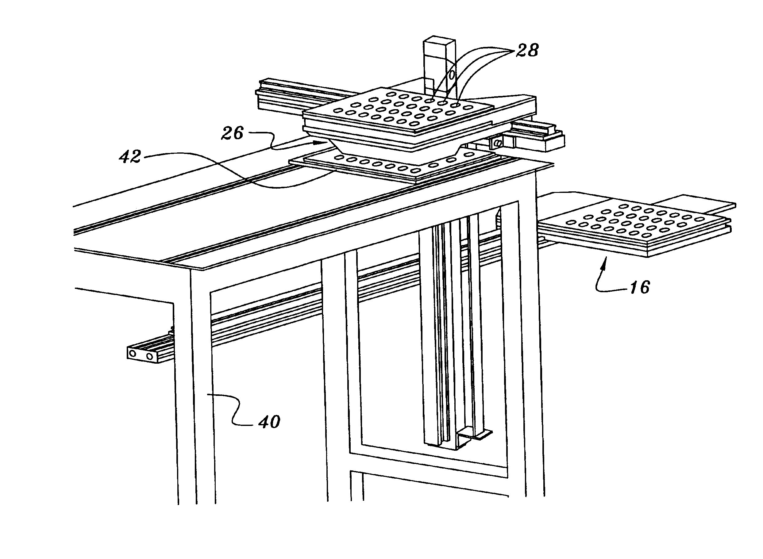
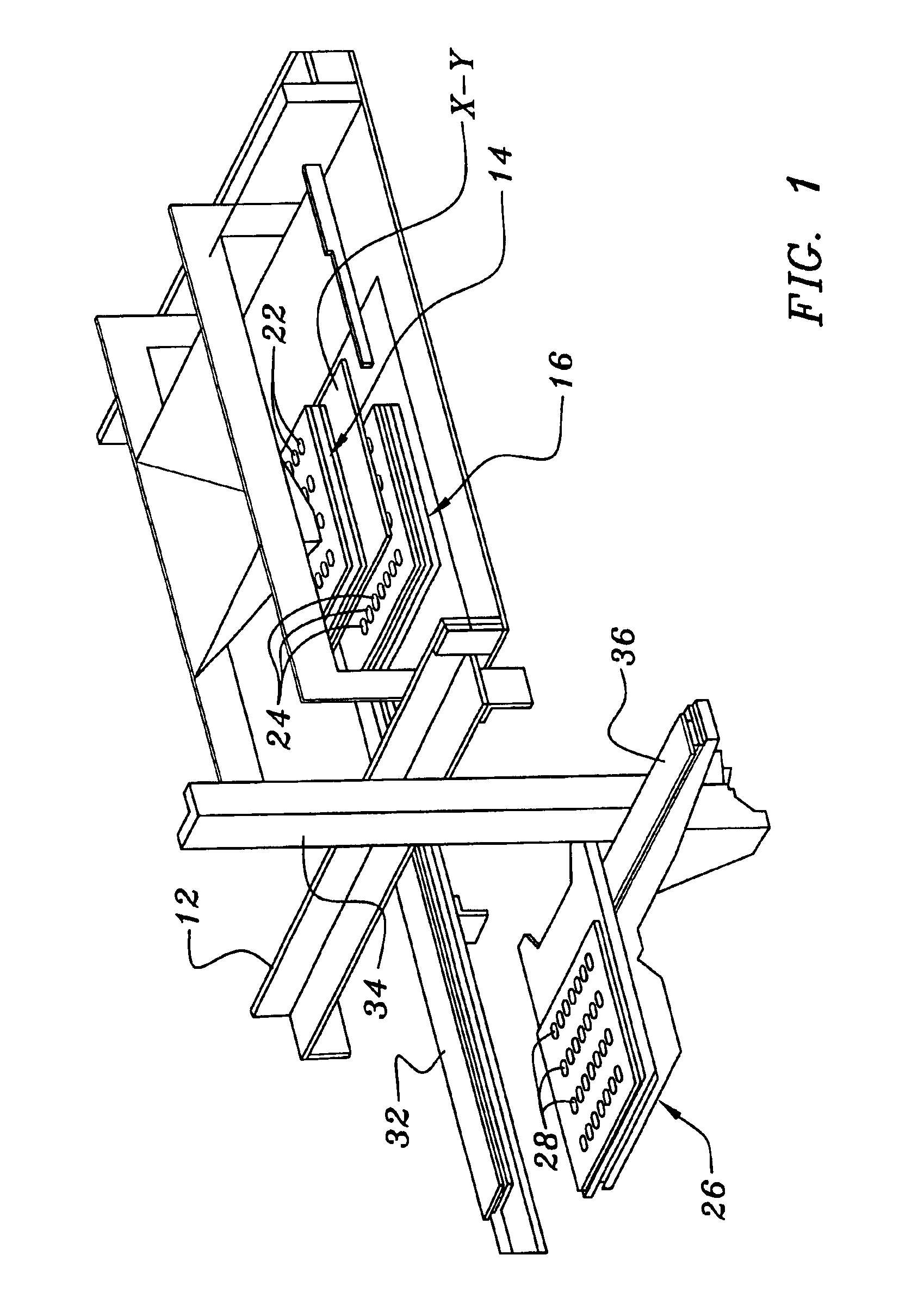
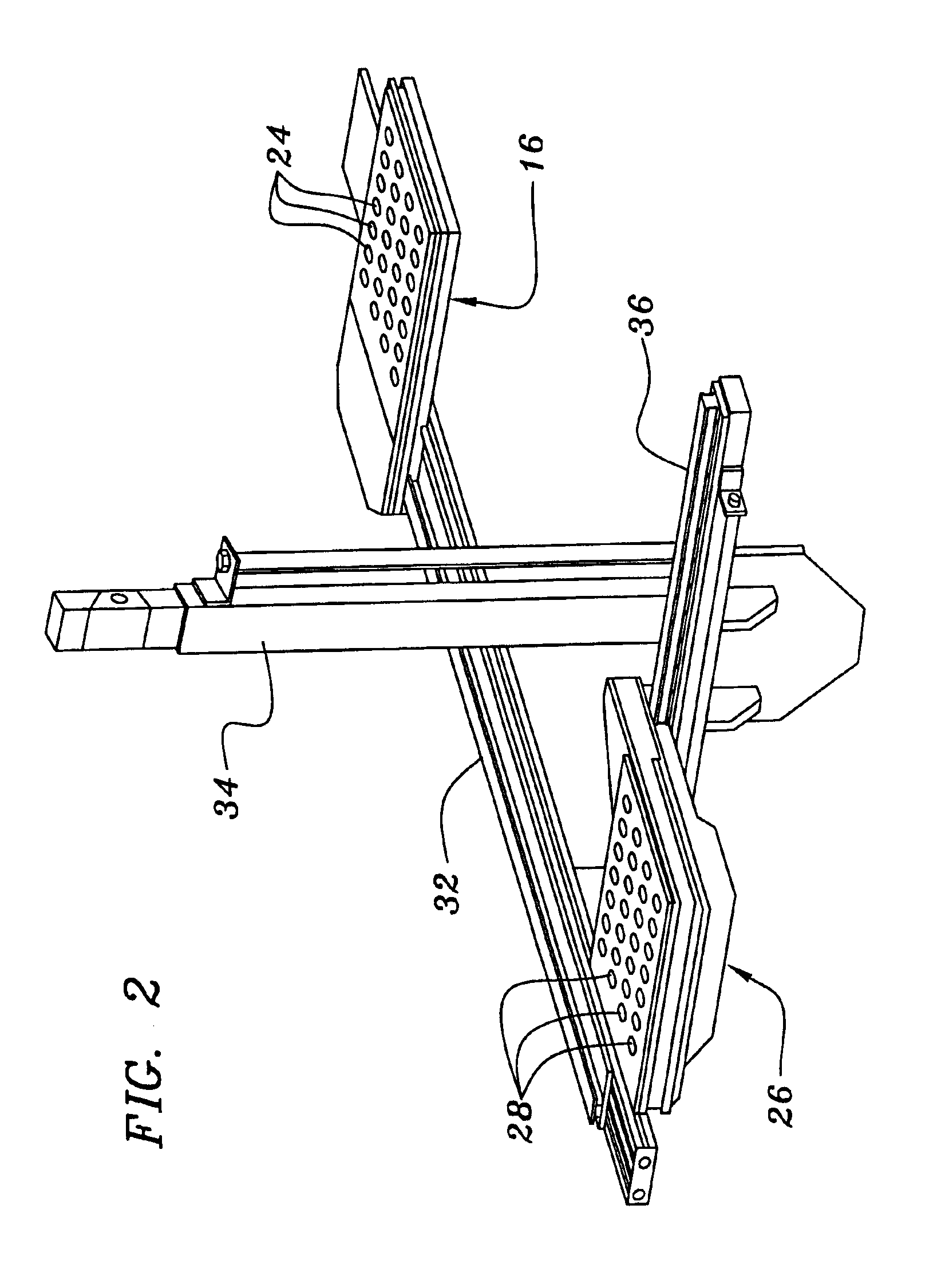
[0022]FIG. 1 illustrates a first preferred exemplary embodiment of the present invention which is shown generally at 10. As illustrated in FIG. 1, a support framework 12 provides a mechanical support for receiving and / or supporting a structure that includes a temporary storage member 14 that is movable in at least 2 axis of displacement. The tray or initial temporary storage member 14 is preferably comprised of a plurality of solid pharmaceutical product cavities arranged in a matrix that corresponds to the arrangement of blister package cavities of a package to be filled. The tray or initial temporary storage member is also known as the upper temporary storage member and is displaced in xy coordinates to selectively locate individual ones of the cavity members beneath a funnel that receives solid pharmaceutical product members that are deposited from a dispensing device or canister.

[0023]A plurality of solid pharmaceutical product dispensers or canisters are arrayed in a cabinet. A...


PUM

PropertyMeasurementUnit
heightaaaaaaaaaa
heightaaaaaaaaaa
gravityaaaaaaaaaa

Abstract

An automated solid pharmaceutical product packaging machine includes a plurality of temporary storage members for receiving a plurality of solid pharmaceutical products in a plurality of cavities. The use of the temporary storage cavities enables the machine to process several prescriptions simultaneously. Advantageously, at least one of the temporary storage members is capable of being automatically displaced in a vertical direction in order to increase the capacity of the overall filling system for processing a greater number of solid pharmaceutical products while minimizing the overall footprint of the device.

Description

RELATED APPLICATIONS[0001]This application is a Continuation-In-Part of application Ser. No. 09 / 704,134, filed Nov. 11, 2000, which is itself a Continuation-In-Part of application Ser. No. 09 / 539,834, filed Mar. 31, 2000.BACKGROUND OF THE INVENTION[0002]1. Field of the Invention[0003]The present invention relates generally to the field of automated solid pharmaceutical product packaging devices. More specifically, the present invention is directed to automated solid pharmaceutical product packaging devices for filling blister packages which are capable of handling a larger variety of pharmaceutical products in a compact structure.[0004]2. Description of the Related Art[0005]Solid pharmaceutical product packaging devices are well-known and exist in a variety of different formats. One well-known variety of these machines is suitable for filling blister package products. In this previous approach, a plurality of automatic dispensing canisters are secured in a common cabinet and these d...

Claims


Application Information

Patent Timeline
Patent Type & Authority Patents(United States)
IPC IPC(8): B65B5/10B65B61/00B65B61/26A61JB65B1/04B65B35/04
CPCB65B5/103B65B35/04B65B61/26
Inventor PETERSON, RAYMOND
Owner MTS MEDICATION TECH INC
Learn More