
Continuous log bucking saw system and method

a continuous feed and sawing technology, applied in the direction of metal sawing devices, stock shearing machines, manufacturing tools, etc., can solve the problems of reducing the yield of a stem, so as to maximize the yield of wood and improve the cutting efficiency

Inactive Publication Date: 2005-08-02
MID SOUTH ENG COMPANY
View PDF14 Cites 19 Cited by
  • Summary
  • Abstract
  • Description
  • Claims
  • Application Information

AI Technical Summary

Benefits of technology

[0019]The invention disclosed herein is designed to use the lineal cutting method while overcoming the historical stoppage problem which occurs when segmenting the stem, by allowing the stem to continue its travel while it is being cut. Substantial slowing or stoppage of the conveyor(s) may cause movement of the stem thereon, and / or it may cause the cutting mechanism to otherwise lose synch with the stem being conveyed. This may cause the bucking system to lose its orientation vis a vis the stem, resulting in mis-cutting that either does not maximize the yield or actually prevents a stem from providing much usable wood. Furthermore, stopping and starting of the conveyor causes unnecessary wear and tear on the machinery.
[0025]Another object of the invention is to provide an improved and efficient cutting system for maximizing the yield of wood from a stem.

Problems solved by technology

Substantial slowing or stoppage of the conveyor(s) may cause movement of the stem thereon, and / or it may cause the cutting mechanism to otherwise lose synch with the stem being conveyed.
This may cause the bucking system to lose its orientation vis a vis the stem, resulting in mis-cutting that either does not maximize the yield or actually prevents a stem from providing much usable wood.
Furthermore, stopping and starting of the conveyor causes unnecessary wear and tear on the machinery.
The lineal cutting method presents each point along a stem to the saw, whereas the number of saw presentation points along a stem in transverse bucking systems are limited by how closely saws can be positioned to each other down the length of the stem.
Many tree trunks are too big and heavy to lift with any speed or stability; their inherent irregularities also hinder clamp gripping.
Moreover, a clamping device will occupy valuable space, likely displacing one or more saw arms.

Method used


Image

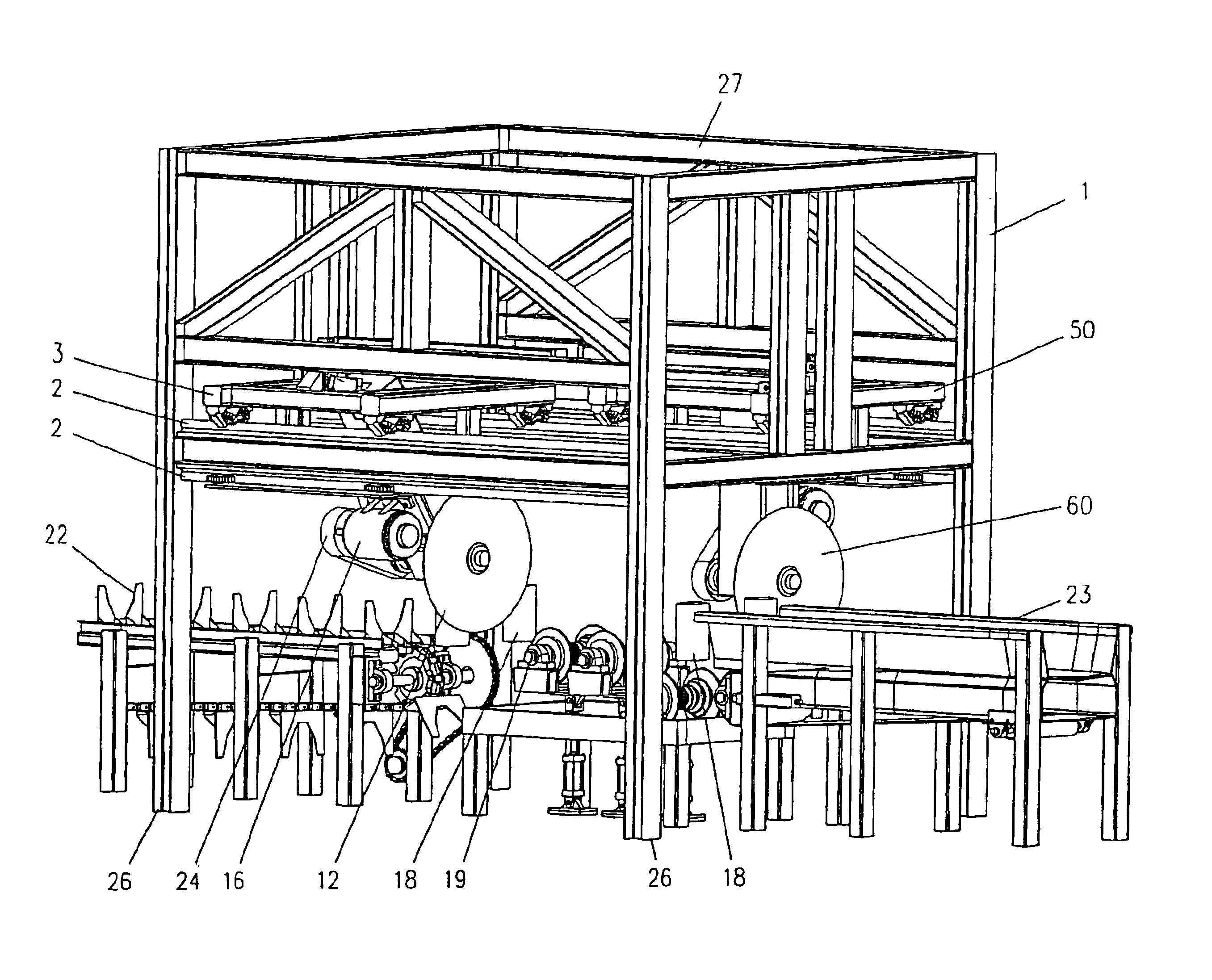
  • Continuous log bucking saw system and method
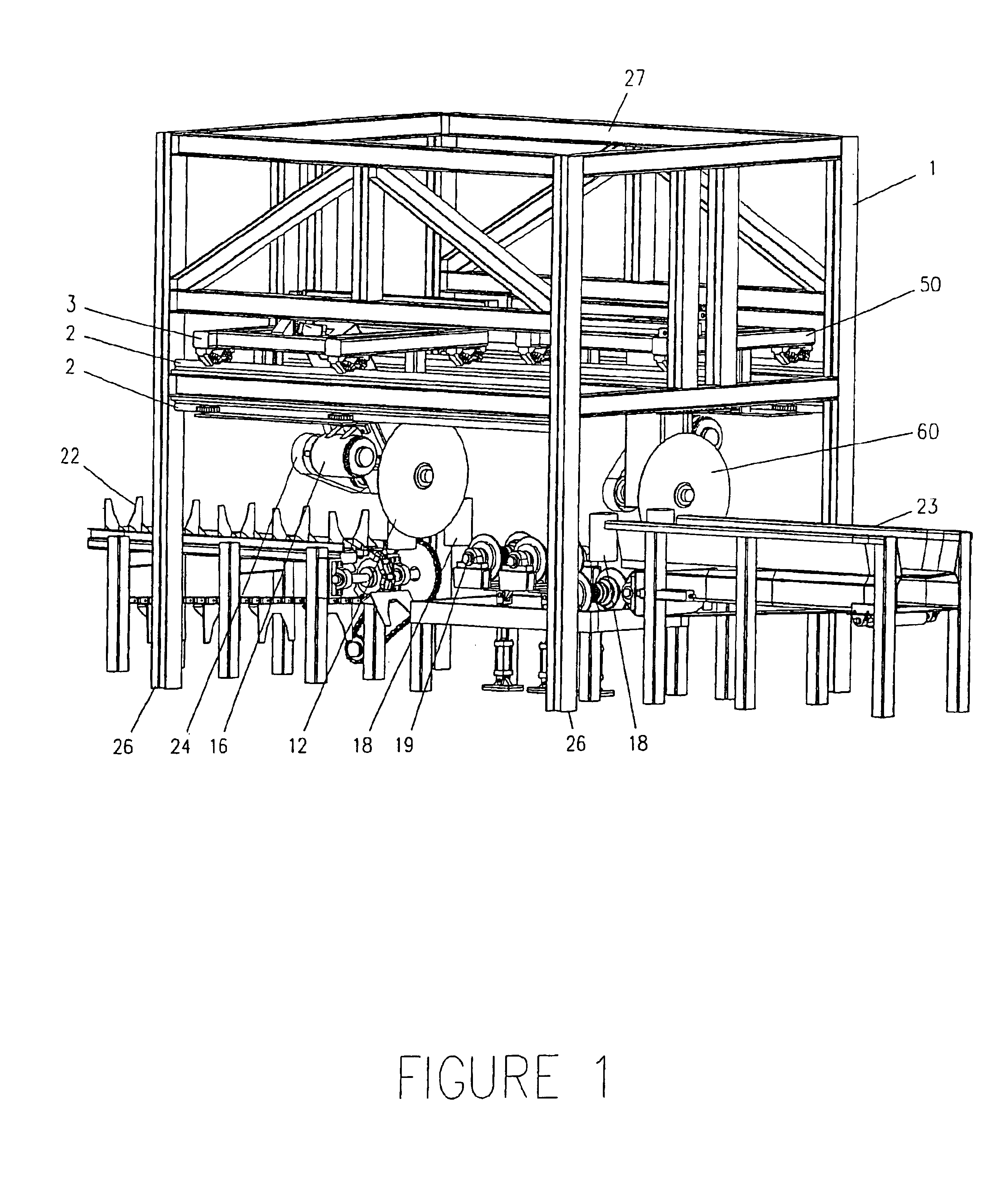
  • Continuous log bucking saw system and method
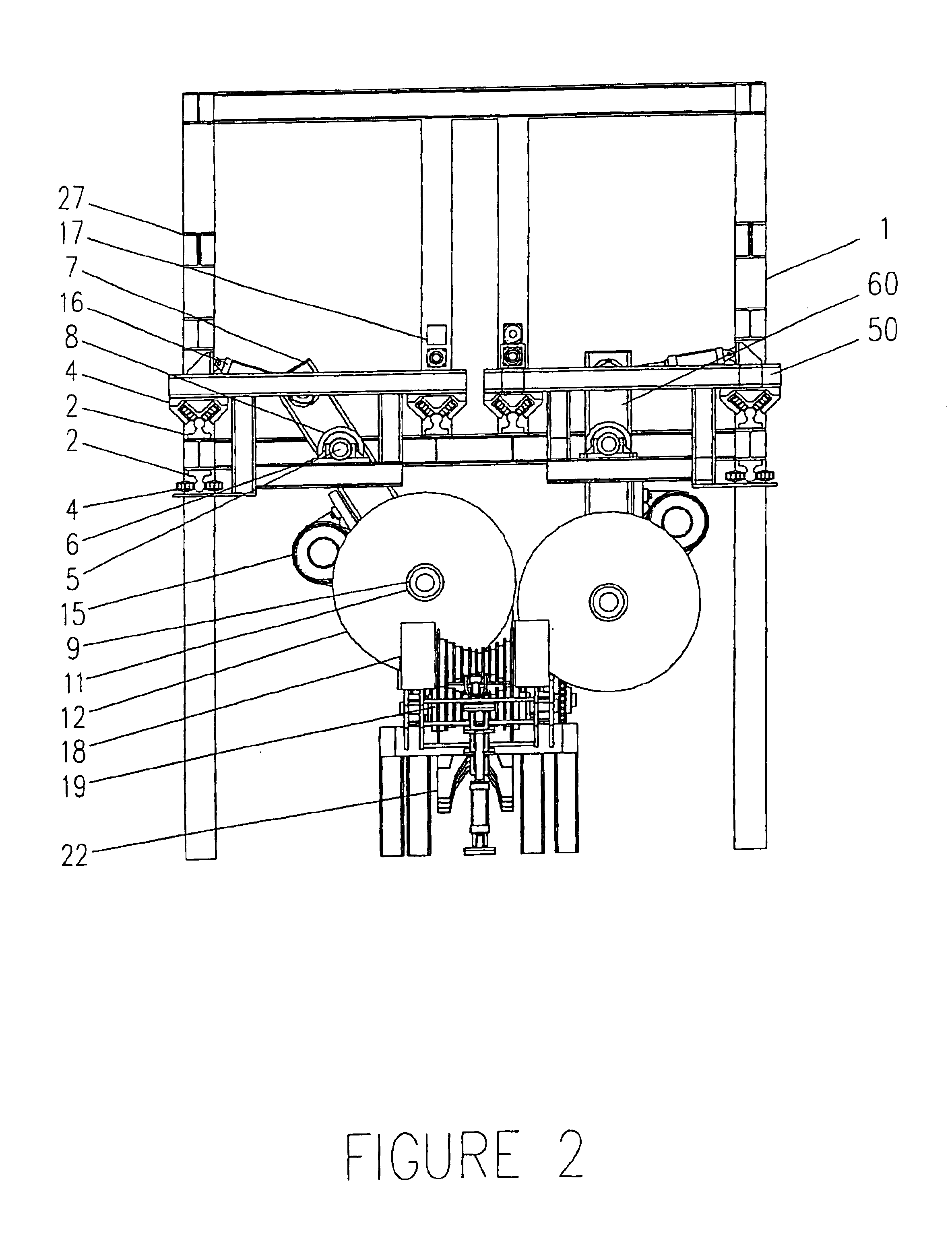
  • Continuous log bucking saw system and method

Examples


Embodiment Construction

[0039]The claims of this invention are to be read to include any legally equivalent device or method. Bforee the present invention is described in detail, it is to be understood that the invention is not limited to the particular configurations, process steps and materials disclosed herein. It is also to be understood that the terminology used herein is not intended to be limiting, since the scope of the present invention will be limited only by the claims and equivalents thereof.

[0040]for the sake of simplicity and to give the claims of this patent application the broadest interpretation and construction possible, the following definitions will apply:

[0041]The word “stem” or derivative thereof essentially means a felled tree that has had its major limbs removed, essentially leaving the central trunk or main body, including any segment of the trunk or main body.

[0042]The word “upstream” essentially means toward the front or leading portion of the invention, as encountered from a con...


PUM

PropertyMeasurementUnit
physical characteristicaaaaaaaaaa
speedaaaaaaaaaa
lengthaaaaaaaaaa

Abstract

A high-throughput, high-end-product-recovery, lineal log bucking device featuring continuous stem travel during the cutting process by using a simple and efficient machinery design for economy of equipment and monies. The apparatus includes: (1) a saw for cutting stem into logs; and (2) apparatus for accelerating the carrier up to the speed of the stem conveyor(s), maintaining the speed during the cut, decelerating the carrier, and then returning the carrier to its starting point.

Description

CROSS REFERENCES TO RELATED APPLICATIONS[0001]Not applicable.FEDERALLY SPONSORED RESEARCH OR DEVELOPMENT[0002]Not applicable.MICROFICHE APPENDIX[0003]Not applicable.BACKGROUND OF THE INVENTION[0004](1) Field of the Invention.[0005]The invention disclosed herein is an automatic tree stem cutting apparatus which is designed to rapidly process substantially tree length stems into logs, poles or other segments for further processing in pole mills, sawmills, plywood plants and the like. This invention relates to a high-speed continuous-feed log bucking system; more particularly, the invention disclosed herein relates to an apparatus for precise dissection of tree trunk stems continuously traveling lineally. The invention described herein essentially executes a cutting pattern on a trunk stem “on the fly”, by receiving input or cut-positioning directives concerning the unique physical characteristics of the workpiece stem traveling lengthwise atop the lineal conveyor(s), the saw carrier t...

Claims


Application Information

Patent Timeline
Patent Type & Authority Patents(United States)
IPC IPC(8): B23D45/20B23D45/00B27B5/00B27B5/18
CPCB23D45/20B27B5/187B27B5/188Y10T83/04Y10T83/155Y10T83/178Y10T83/4659Y10T83/4664Y10T83/4691Y10T83/4737Y10T83/4749Y10T83/4757Y10T83/533Y10T83/536Y10T83/538Y10T83/543Y10T83/6668Y10T83/7693Y10T83/7784Y10T83/7788Y10T83/7793
Inventor CULPEPPER, T. MARKHORMAN, WAYNE A.HUNNICUTT, JOHN M.
Owner MID SOUTH ENG COMPANY
Learn More