
Method and apparatus for fused silica production

a technology of fused silica and production method, which is applied in the field of porous refractories and fused silica production furnaces, can solve the problems of difficult control of pore size, pore structure and pore distribution, and each individual brick and fastener is a possible failure point in the furnace crown, so as to facilitate purification of refractory materials and reduce contaminants

Inactive Publication Date: 2005-08-02
CORNING INC
View PDF13 Cites 0 Cited by
  • Summary
  • Abstract
  • Description
  • Claims
  • Application Information

AI Technical Summary

Benefits of technology

[0012]The furnaces and methods of the present invention are expected to provide a furnace environment having fewer contaminants. In particular, by using foamed refectories that do not use cork or other burnout material to form the pores in the refractories, fewer impurities should be present in the refractory. In addition, a network of interconnected pores facilitates purification of the refractory material by using the halogen gas treatment process described in U.S. Pat. No. 6,174,509.

Problems solved by technology

One disadvantage associated with using bricks is that each individual brick and fastener is a possible failure point in the furnace crown.
One disadvantage of this process is that the pore size, pore structure and pore distribution are difficult to control.
Although the process provides a porous refractory brick, it is difficult to form a network of interconnected pores in the brick.
Another disadvantage of this process is that it is difficult to obtain a pore surface area greater than 0.5 m2 / g, as measured by the BET method.
It is also difficult to produce a brick having porosity greater than 50%, and the density of bricks produced by this method exceeds 2 g / cm3.

Method used


Image

  • Method and apparatus for fused silica production
  • Method and apparatus for fused silica production

Examples


Embodiment Construction

[0015]Before describing several exemplary embodiments of the invention, it is to be understood that the invention is not limited to the details of construction and the arrangement of components set forth in the following description or illustrated in the drawings. The invention is capable of other embodiments and of being practiced or being carried out in various ways.

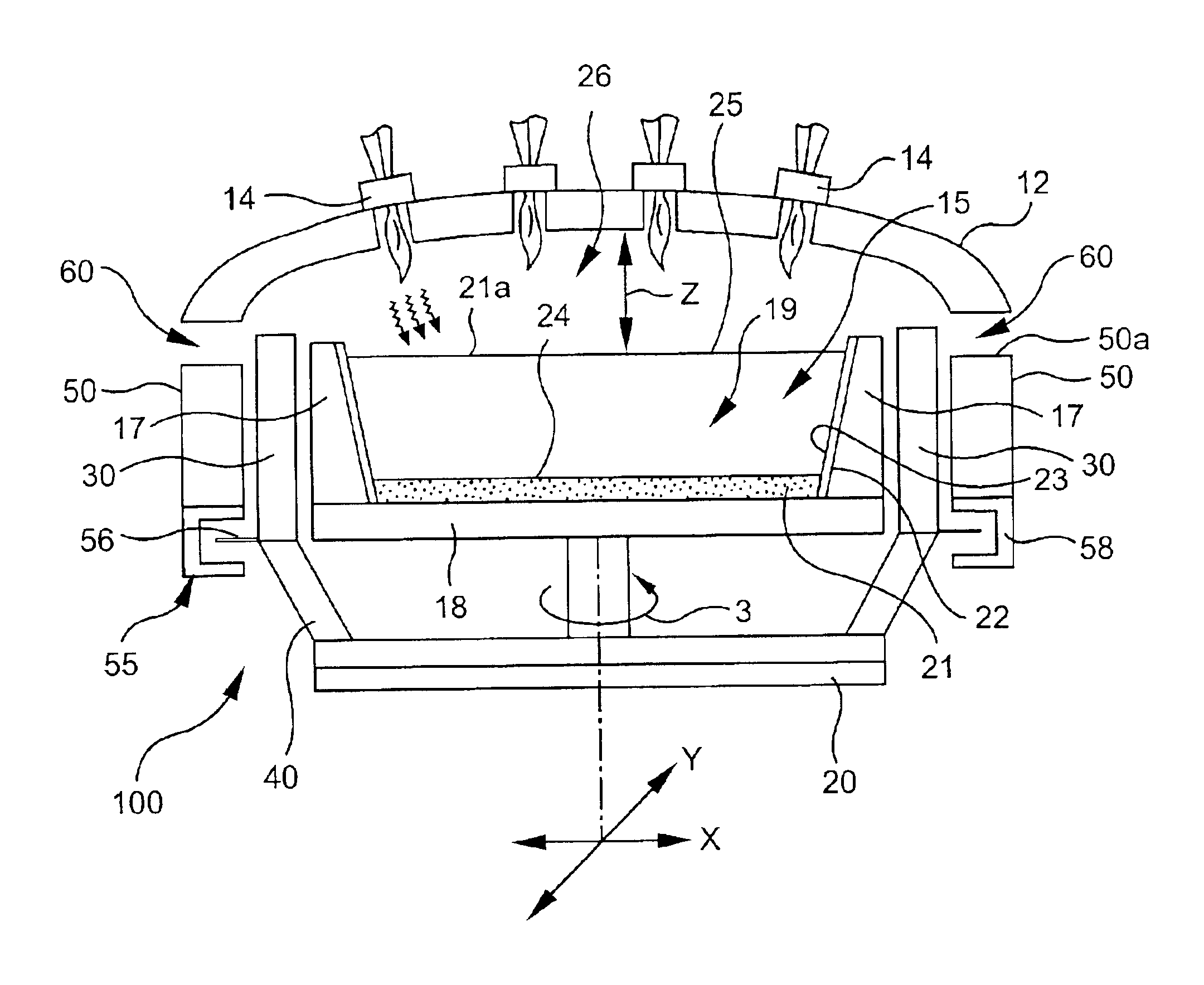
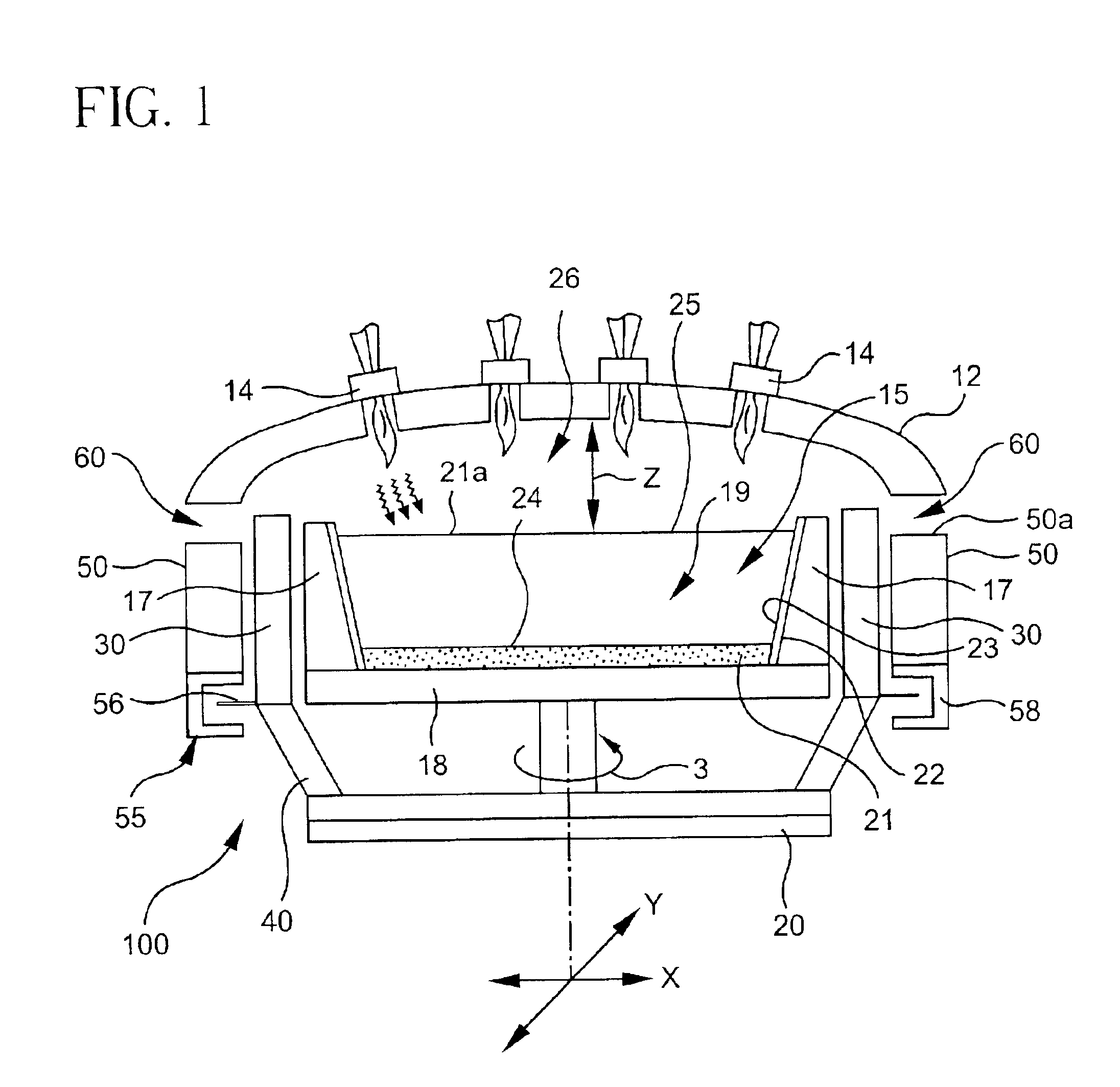
[0016]The manufacture of high purity fused silica is known and described in U.S. Pat. No. 5,043,002. In general, the manufacture of fused silica involves the introduction of a silicon-containing precursor into a flame to produce fused silica particles or soot. The flame is provided by a burner, and typically multiple burners 14, in a furnace of the type shown in FIG. 1 that includes a crown 12 and a collection surface. The furnace of the present invention and may or may not include a collection cup or containment vessel. The particles or soot are collected on the collection surface and consolidated to form a boule. Thi...


PUM

PropertyMeasurementUnit
porosityaaaaaaaaaa
densityaaaaaaaaaa
temperaturesaaaaaaaaaa

Abstract

A fused silica production furnace and methods of producing fused silica are disclosed. The furnace and the methods involve using a foamed refractory having a network of interconnected pores.

Description

CROSS REFERENCE TO RELATED APPLICATIONS[0001]This application claims the benefit of U.S. Provisional Application Ser. No. 60 / 257,710, filed Dec. 21, 2000 entitled Foamed Refractories for HPFS Manufacture, by Michael D. Harris and Robert S. Pavlik.FIELD OF THE INVENTION[0002]This invention relates to refractories. More particularly, the invention relates to porous refractories and fused silica production furnaces that utilize porous refractories.BACKGROUND OF THE INVENTION[0003]Fused silica and ultra low expansion glass production furnaces produce boules by the deposition of soot or silica particles produced from vaporous or liquid reactants and consolidation of the soot. Such metal oxide soot can be produced by flame hydrolysis of precursors in the form of a vapor or atomized liquid carried by a carrier gas into the flame of a burner or multiple burners. The furnace is surrounded by refractory materials. Refractory materials in these furnaces are exposed to temperatures exceeding 16...

Claims


Application Information

Patent Timeline
Patent Type & Authority Patents(United States)
IPC IPC(8): C03B19/00C03B19/14C03B5/43
CPCC03B19/1407C03B19/14
Inventor HARRIS, MICHAEL D.PAVLIK, JR., ROBERT S.
Owner CORNING INC
Learn More