Leakage current or resistance measurement method, and monitoring apparatus and monitoring system of the same
- Summary
- Abstract
- Description
- Claims
- Application Information
AI Technical Summary
Benefits of technology
Problems solved by technology
Method used
Image
Examples
first embodiment
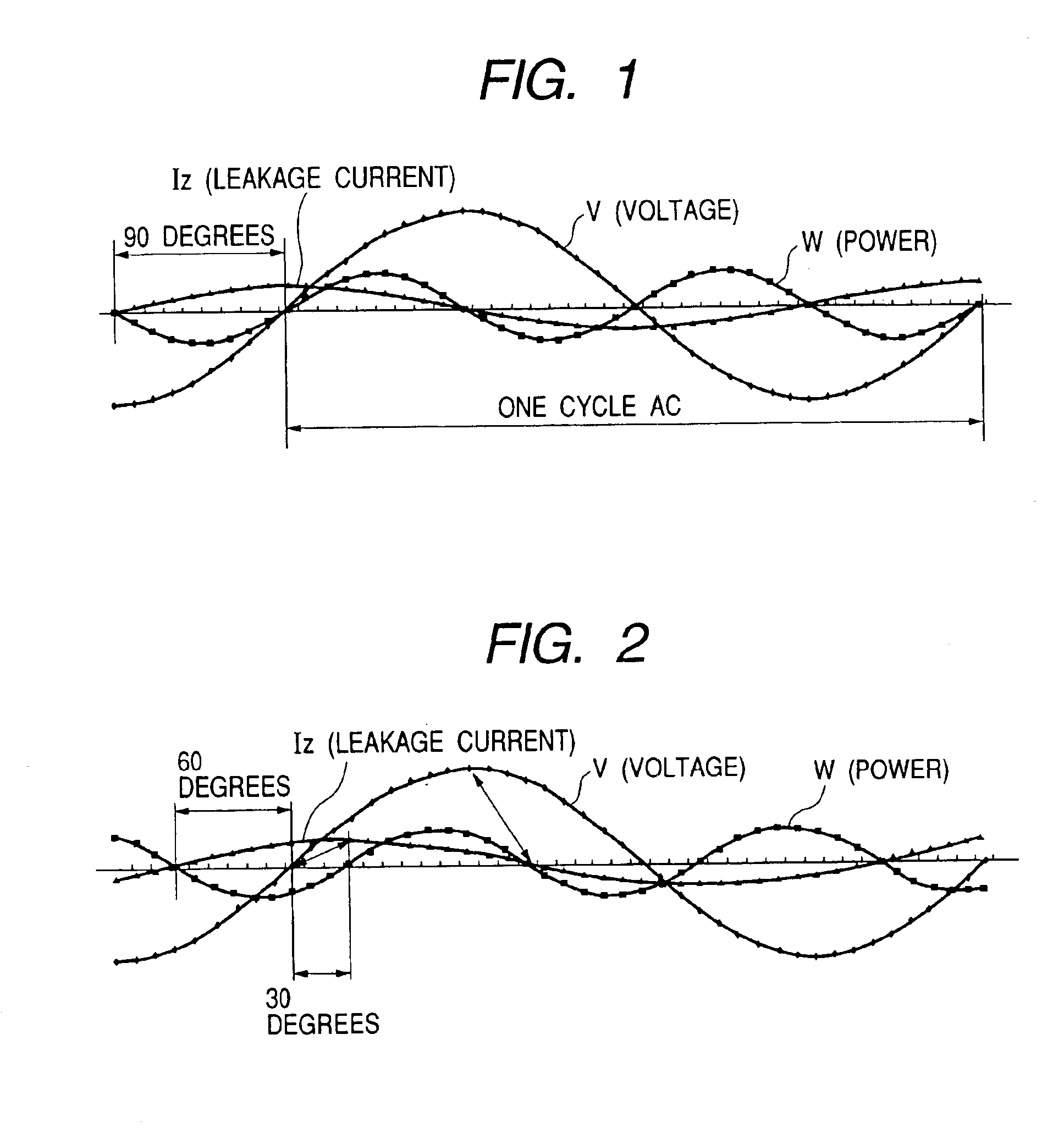
[0038]FIG. 1 is a waveform diagram for describing the leakage current measurement method in accordance with the present invention, and the principle of calculation of the resistance component current from the leakage current by use of this waveform diagram. The waveform shows a waveform for the case that the primary circuit 42 of the distribution system shown in FIG. 9 is a single-phase circuit, in which the output of the current transformer 46 and the voltage waveform generated from the primary circuit 42 are represented by the time axis.
[0039]In FIG. 1, Iz denotes the leakage current, V denotes the voltage, W denotes the leakage current power, and dots of each waveform show the sampling value. The phase of the leakage current Iz proceeds 90 degrees ahead of the voltage if no active component current Igr is involved.
[0040]The power W of the AC circuit is calculated by use of the equation W=VI cos Φ according to the AC theory, wherein V denotes the circuit voltage, I denotes the loa...
second embodiment
[0044]Next, the present invention will be described with reference to FIG. 2.
[0045]FIG. 2 is a waveform diagram for describing the second embodiment of the leakage current measurement method in accordance with the present invention, and shows the voltage waveform, leakage current waveform, and leakage current power waveform for the case in which the power is supplied to the load with two-wire drawing from the first phase (RS) of the three-phase AC. In this case, the phase of the leakage current Iz proceeds 60 degrees ahead of the voltage (line voltage) if only the electrostatic capacity is involved. The reason is that the line voltage in the three-phase AC proceeds 30 degrees ahead of the phase voltage. Therefore, the second embodiment is characterized in that the instantaneous line voltage value is stored when the leakage current and the line voltage are sampled and the power calculated by use of the instantaneous leakage current value and the stored instantaneous voltage value tha...
third embodiment
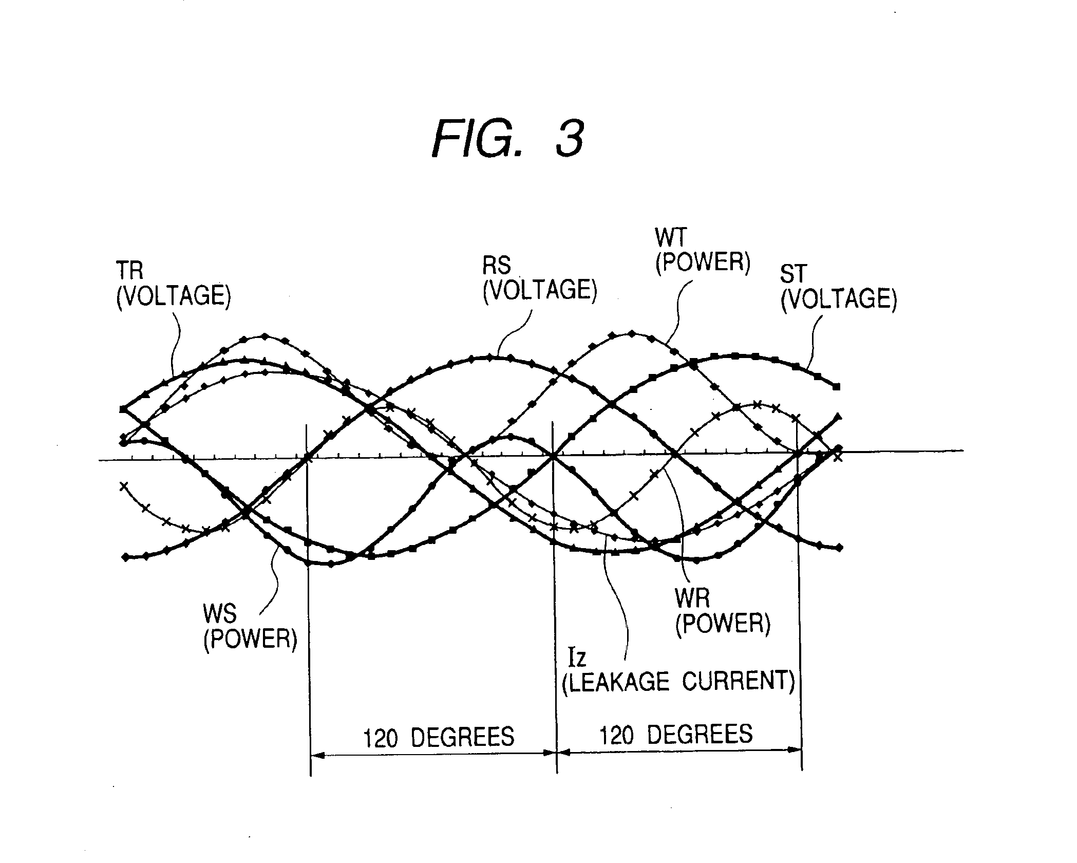
[0046]Next, the present invention will be described with reference to FIG. 3.
[0047]FIG. 3 is a waveform diagram for describing the third embodiment of the leakage current measurement method in accordance with the present invention, and shows the voltage waveform of the three-phase AC (voltage RS, voltage ST, and voltage TR) and the leakage current waveform Iz of the three-phase AC. The voltage of the respective voltage waveforms of the three-phase AC is the line voltage. As it is well known, respective line voltages proceed with intervals of 120 degrees phase difference. When the leakage current is sampled correspondingly to each voltage waveform, the leakage current Iz proceeds 60 degrees ahead of the line voltage as shown in FIG. 3 in the case that only the electrostatic capacity is involved similarly to the second embodiment. Therefore, the instantaneous line voltage values are stored when the leakage current and instantaneous values of each line voltage waveform are sampled, eac...
PUM
 Abstract
Description
Claims
Application Information
 - R&D
- Intellectual Property
- Life Sciences
- Materials
- Tech Scout
- Unparalleled Data Quality
- Higher Quality Content
- 60% Fewer Hallucinations
Browse by: Latest US Patents, China's latest patents, Technical Efficacy Thesaurus, Application Domain, Technology Topic, Popular Technical Reports.
© 2025 PatSnap. All rights reserved.Legal|Privacy policy|Modern Slavery Act Transparency Statement|Sitemap|About US| Contact US: help@patsnap.com


