
Disk drive comprising a cover shaped to improve radial and axial shrouding

a technology of radial and axial shrouding and disk drives, which is applied in the direction of casings/cabinets/drawers, instruments, casings/cabinets/drawers, etc., can solve the problems of increased internal hda temperature, increased spindle motor current, and increased spindle motor rotational speed, etc., to achieve the effect of improving the shrouding

Inactive Publication Date: 2005-07-26
WESTERN DIGITAL TECH INC
View PDF22 Cites 71 Cited by
  • Summary
  • Abstract
  • Description
  • Claims
  • Application Information

AI Technical Summary

Benefits of technology

[0010]The present invention may be regarded as a disk drive with improve shrouding, comprising a disk, a spindle motor for rotating the disk, a head, an actuator arm for actuating the head radially over the disk, a base, and a cover attached to the base to form a head disk assembly chamber. The cover comprises an inner surface and an outer surface, and a shroud extending axially from the inner surface into the head disk assembly chamber substantially enveloping the periphery of the disk, including at least part of the periphery coextensive with the actuator arm, to provide radial shrouding of the disk.
[0012]The present invention may be regarded as a method of manufacturing a disk drive with improved shrouding. A shroud is formed in a cover of a head disk assembly (HDA). A disk, a head, an actuator arm for actuating the head radially over the disk, and a motor for rotating the disk, are disposed into the HDA. The cover is attached at a base of the HDA such that the shroud substantially envelops the periphery of the disk, including at least part of the periphery coextensive with the actuator arm, to provide radial shrouding of the disk.

Problems solved by technology

However, there are a number of problems associated with higher spindle motor rotational speeds.
One problem is increased internal air turbulence in the HDA which can excite disk flutter modes, thereby setting up resonances that can cause the heads 114 to move off track during read and write operations.
Another problem associated with higher spindle motor rotational speeds is increased windage drag on the disks, thereby causing an increase in spindle motor current and elevated internal HDA temperature.
Yet another problem associated with higher spindle motor rotational speeds is an increase in the acoustic noise radiated by the disk drive.
These precision manufacturing constraints increase the complexity and cost of the disk drive.

Method used


Image

  • Disk drive comprising a cover shaped to improve radial and axial shrouding
  • Disk drive comprising a cover shaped to improve radial and axial shrouding
  • Disk drive comprising a cover shaped to improve radial and axial shrouding

Examples


Embodiment Construction

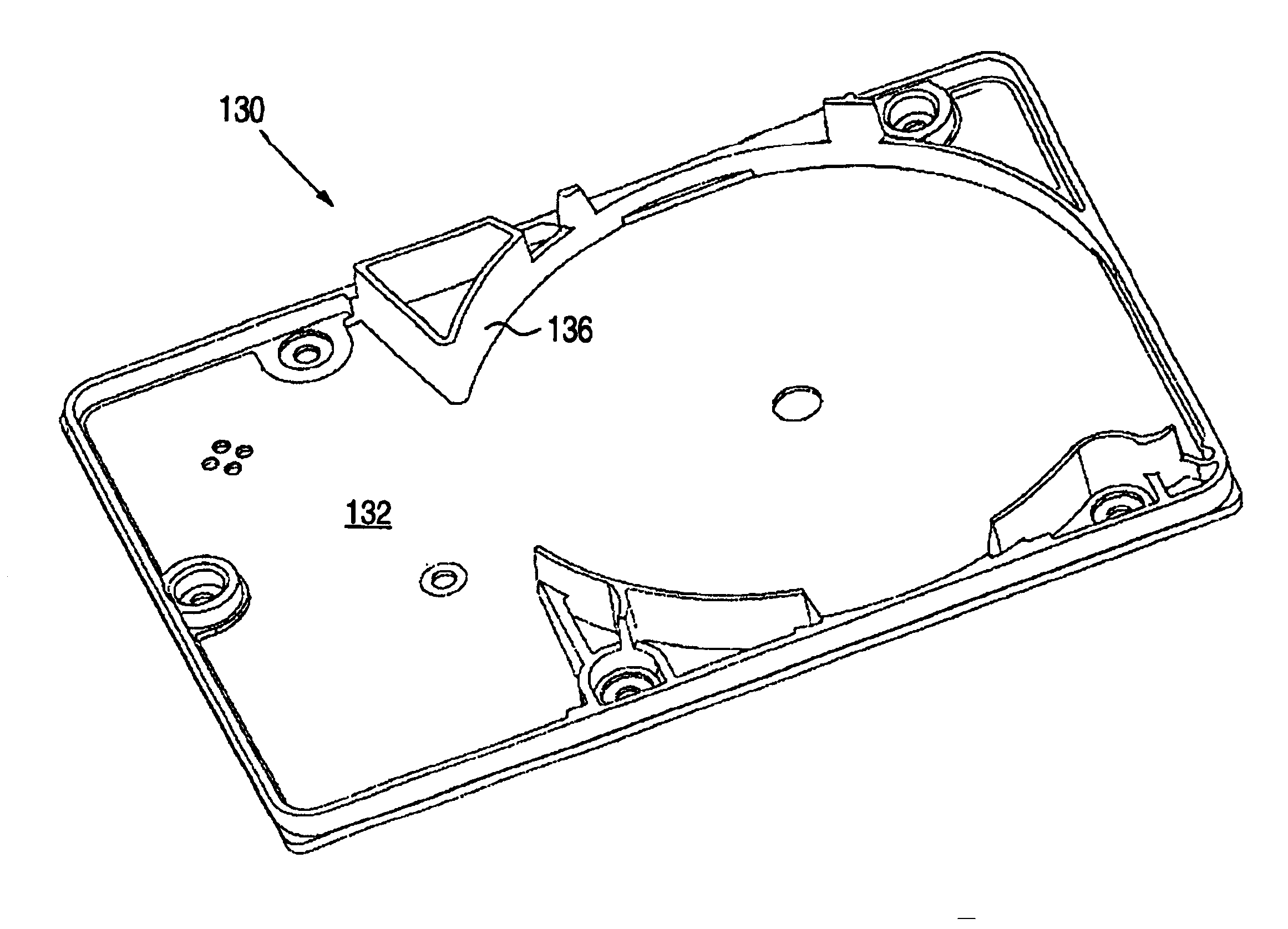
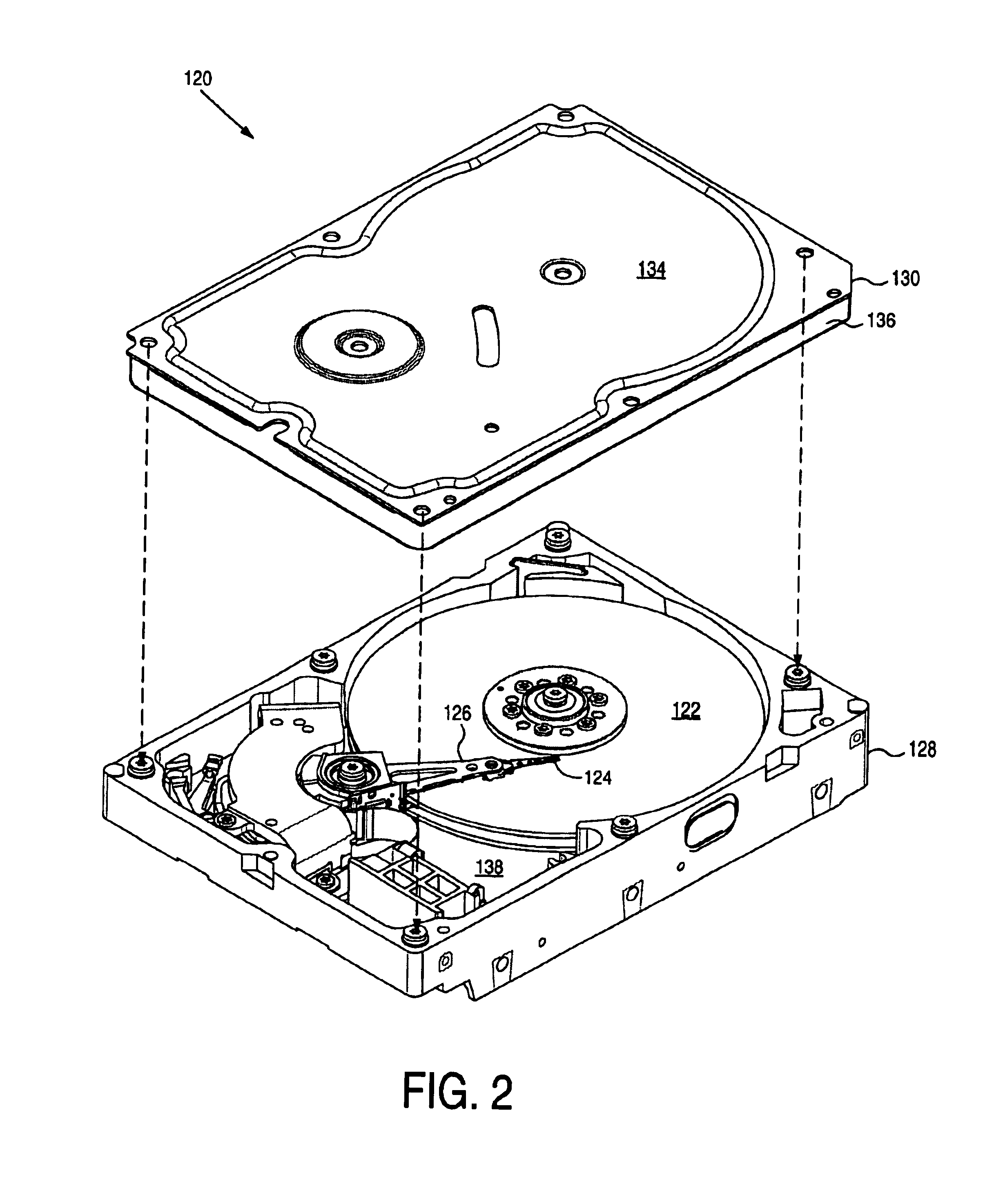
[0019]FIG. 2 shows a disk drive 120 according to an embodiment of the present invention comprising a disk 122, a spindle motor for rotating the disk 122, a head 124, an actuator arm 126 for actuating the head 124 radially over the disk 122, a base 128, and a cover 130 attached to the abase 128 to form a head disk assembly (HDA) chamber. The cover 130 comprises an inner surface 132 (see FIG. 3A) and an outer surface 134. As shown in FIG. 3A, the cover 130 further comprises a shroud 136 extending axially from the inner surface 132 into the HDA chamber substantially enveloping the periphery of the disk 122, including at least part 138 of the periphery coextensive with the actuator arm 126, to provide radial shrouding of the disk 122.

[0020]The shroud 136 may be realized using any suitable means for extending a radial shroud from the inner surface 132 of the cover 130 such that the periphery of the disk 122 is substantially enveloped (including gap 138). In one embodiment, the shroud 136...


PUM

PropertyMeasurementUnit
rotational speedaaaaaaaaaa
rotational speedsaaaaaaaaaa
temperatureaaaaaaaaaa

Abstract

A disk drive with improved shrouding is disclosed. The disk drive comprises a disk, a spindle motor for rotating the disk, a head, an actuator arm for actuating the head radially over the disk, a base, and a cover attached to the base to form a head disk assembly chamber. The cover comprises an inner surface and an outer surface, and a shroud extending axially from the inner surface into the head disk assembly chamber substantially enveloping the periphery of the disk, including at least part of the periphery coextensive with the actuator arm, to provide radial shrouding of the disk.

Description

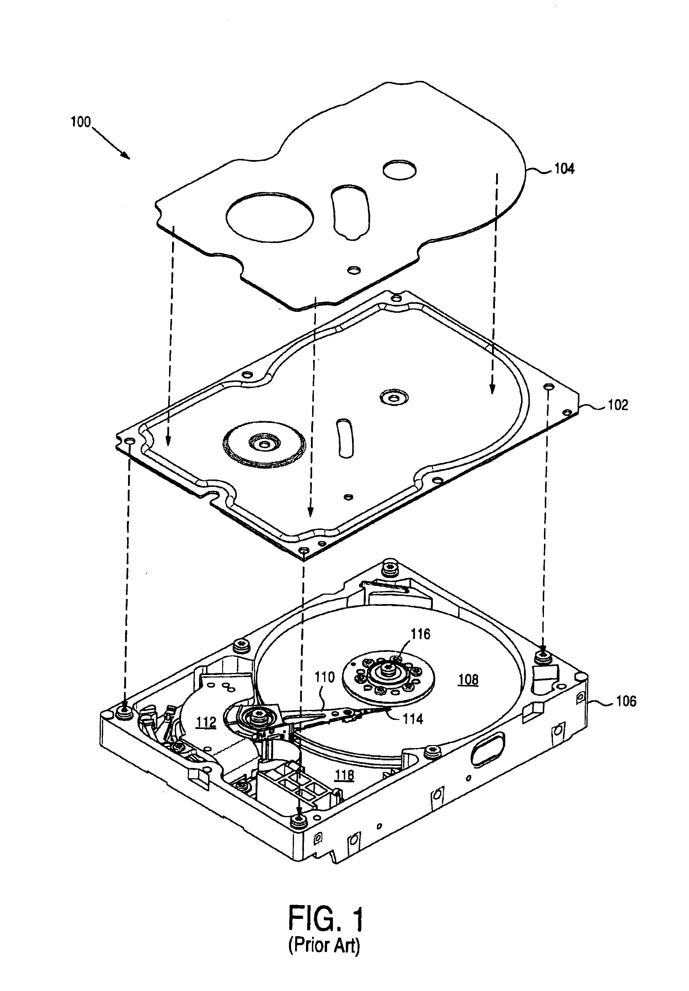
BACKGROUND OF THE INVENTION[0001]1. Field of the Invention[0002]The present invention relates to disk drives for computer systems. More particularly, the present invention relates to a disk drive with improved shrouding.[0003]2. Description of the Prior Art[0004]A computer system usually includes one or more disk drives for economical, non-volatile data storage. FIG. 1 shows a typical prior art disk drive 100 which includes a housing formed by fitting a cover comprising an inner layer 102 and an outer layer 104 to a base 106 to create a sealed head disk assembly (HDA) chamber. The HDA includes one or more disks 108 stacked in a spaced-apart relationship on a spindle motor hub and rotated by a spindle motor (not shown). The disks 108 rotate in close proximity to a head 114 that is disposed by means of a head gimbal assembly (HGA) attached to one of a plurality of actuator arms 110.[0005]The spindle motor includes a stationary element such as a fixed spindle shaft 116 affixed to the d...

Claims


Application Information

Patent Timeline
Patent Type & Authority Patents(United States)
IPC IPC(8): G11B33/14G11B25/04
CPCG11B25/043G11B33/148
Inventor BUTLER, WALTER W.
Owner WESTERN DIGITAL TECH INC
Learn More