
High intensity light source arrangement

Inactive Publication Date: 2005-07-26
CHEN AMY YUN
View PDF3 Cites 7 Cited by
  • Summary
  • Abstract
  • Description
  • Claims
  • Application Information

AI Technical Summary

Benefits of technology

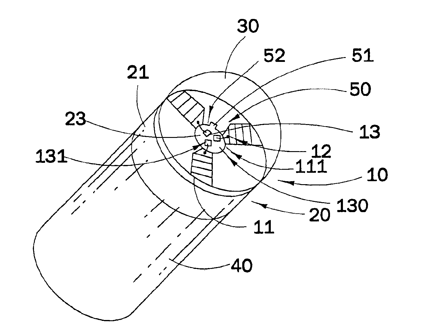
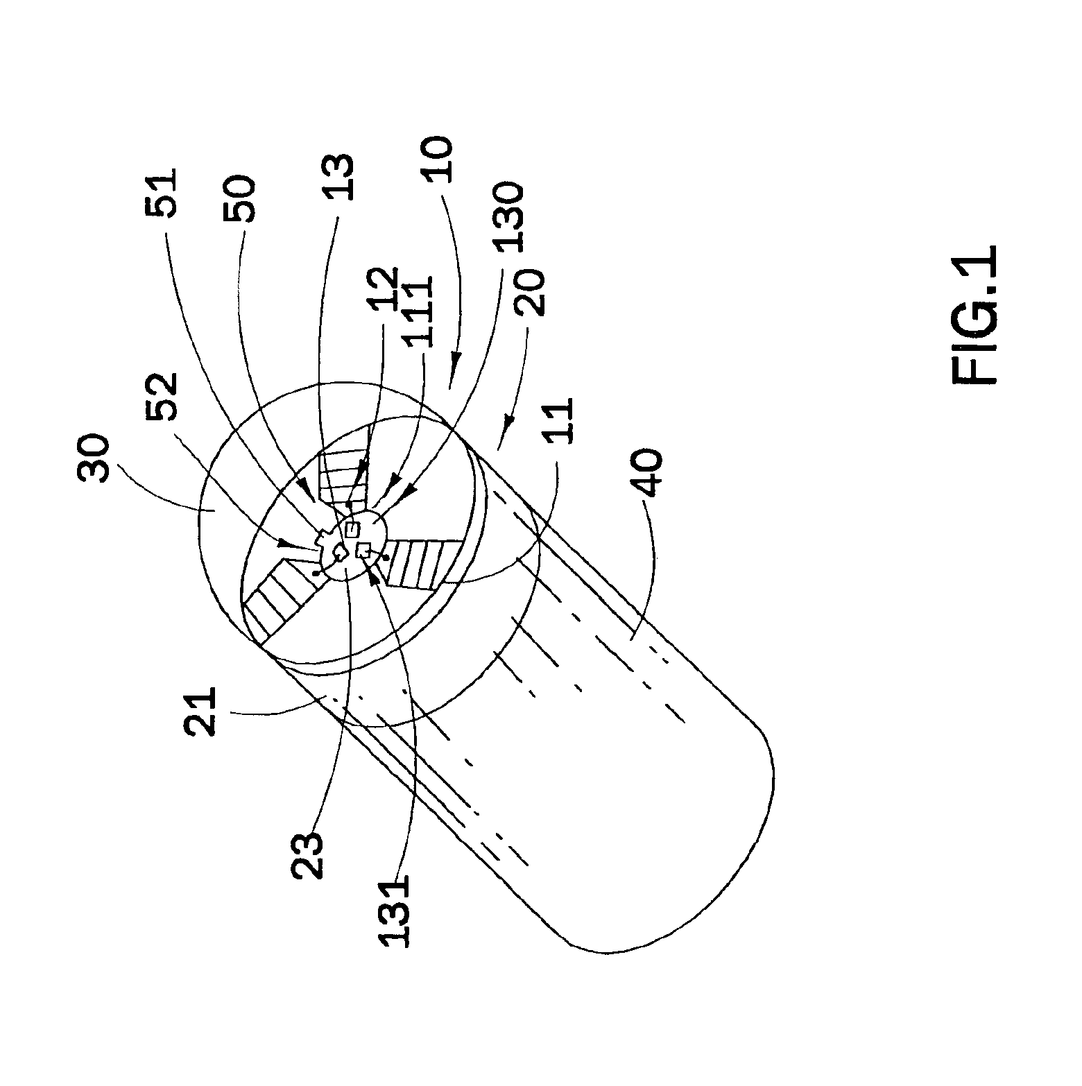
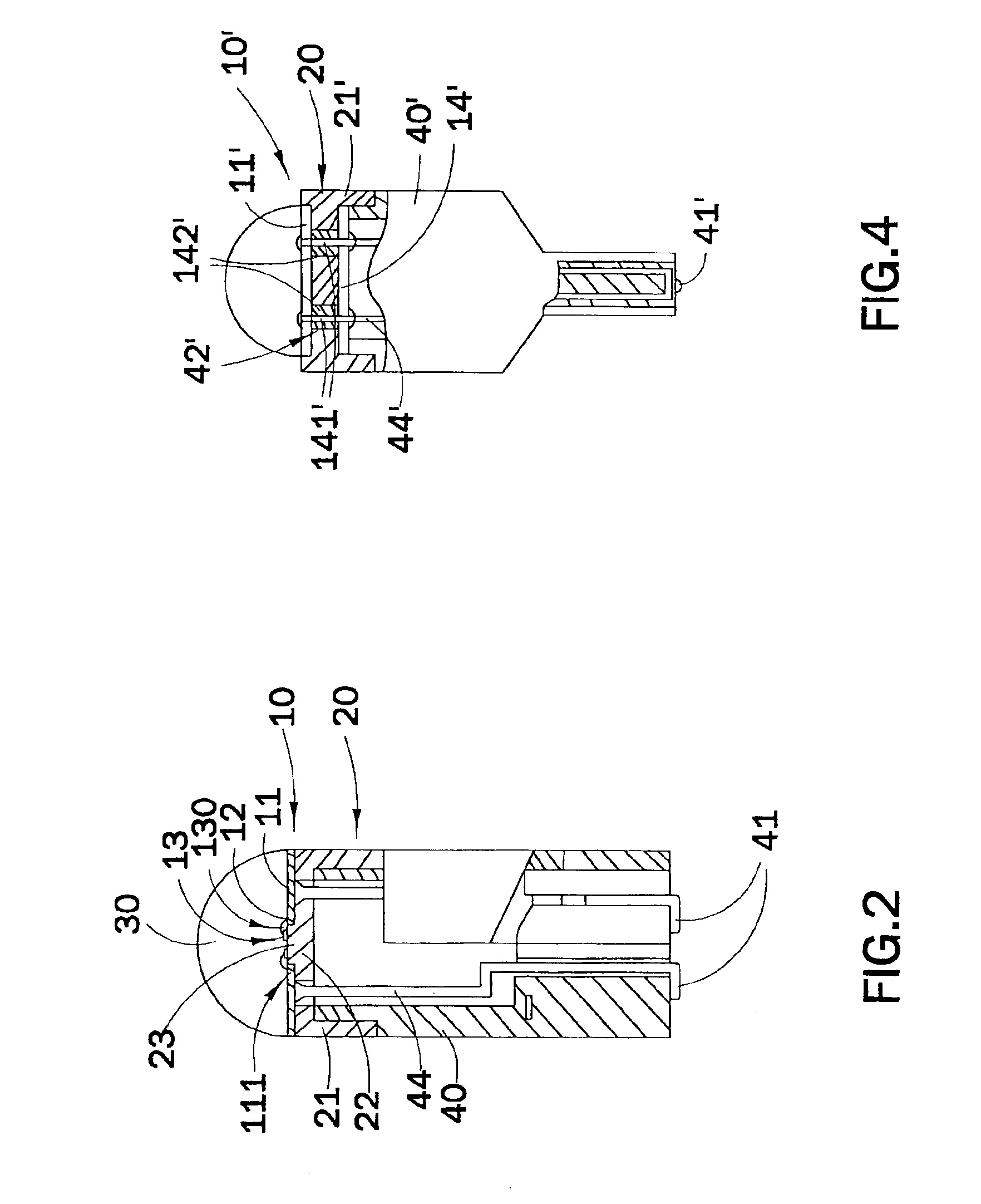
[0010]A main object of the present invention is to provide a high intensity light source arrangement which can prolong the service life span of the high intensity light source arrangement by better dissipating and reducing the heat generated.
[0011]Another object of the present invention is to provide a high intensity light source arrangement which greatly increases the brightness of the light emitted, wherein the light source arrangement is capable of providing a light intensity up to five times or more of a conventional LED.
[0012]Another object of the present invention is to provide a high intensity light source arrangement which comprises a heat dissipation unit directly mounted underneath a circuit board for efficiently dissipating heat therefrom. Therefore, a plurality of luminary elements is capable of electrifying with the terminals on the circuit board.
[0015]Another object of the present invention is to provide a high intensity light source arrangement wherein a fluorescent layer is evenly coated on an inner surface of a head cover of the high intensity so as to enhance the white light evenly dispersed therefrom.

Problems solved by technology

Although the LED has excellent properties of low power consumption and instant light emission, the relatively small light intensity and lighting emission angle of the LED make it not suitable to use for illumination or even apply in some specific area such as traffic light, signboard light, vehicle brake light and signal light, and airport guiding lighting.
However, due to the structure of the LED, when increasing the current, heat generated from the LED will burn the LED.
In addition, the major drawback of the LED is that the LED cannot produce white light.
However, the fluorescent layer cannot be evenly applied on the inner surface of the reflexive cover so that the white light will not be evenly dispersed from the reflexive cover so as to provide an uneven intensity of the white light.

Method used


Image

  • High intensity light source arrangement
  • High intensity light source arrangement
  • High intensity light source arrangement

Examples


second embodiment

[0064]Referring to FIG. 8, a second preferred embodiment of the present invention is illustrated, which is another alternative application of the first preferred embodiment, wherein a plurality of luminary units 10 (10′) are supported around a heat dissipation unit 200 in an evenly distributing manner. the heat dissipation unit 200 has a plurality of mounting through slots 201 spacedly formed around a curved outer surface of the heat dissipation unit 200, wherein the luminary units 10 (10′) are fittedly mounted on the mounting through slots 201 of the heat dissipation unit 200 respectively. Each of the luminary units 10 (10′) is arranged to be protected by the head shelter 30 (30′) in such a manner that the head shelters 30′ are outwardly protruded from the surface of the heat dissipation unit 200, as shown in FIG. 8. Similarly, a base housing 400 supports the heat dissipation unit 200, wherein electric input connecters 410 provided at a bottom end of the base housing 400 electrica...

third embodiment

[0066]Referring to FIG. 9, the high intensity light source arrangement is illustrated, which is another alternative application of the above first preferred embodiment, wherein the base housing 40″ is modified to further comprise a base 43″ and a pair of supporting arms 42″ upwardly extending from the base 43″ for suspending the luminary unit 10″ and the heat dissipation unit 20″. In order words, the heat dissipation unit 20″ is securely supported between two free ends of the supporting arms 42″. The luminary unit 10″ is arranged to face towards the base 43″ in such a manner that the emitted light from the luminary unit 10″ is distributing towards the base housing 40″.

[0067]It is worth to mention that the high intensity light source arrangement of the third embodiment is capable of incorporating with a vehicle signal light having a concave reflective body, wherein the luminary unit 10″ is positioned at a focus point of the concave reflective body in such a manner that the light from...

fourth embodiment

[0070]Referring to FIGS. 12 to 14, a fourth preferred embodiment of the high intensity light source arrangement is illustrated, wherein the luminary units A10 of the fourth embodiment are arranged to emit lights radially so as to enhance the light intensity of the present invention.

[0071]According to the fourth embodiment, the high intensity light source arrangement comprises a base housing A40, at least a heat dissipation unit A20 and at least a luminary unit A10. The base housing A40 further comprises a base A43 and an elongated central shaft A45 extended vertically from the base A43. There are four heat dissipation units A20 spacedly mounted on the central shaft A45 and extended along the central shaft A45, wherein the luminary units A10 are radially supported on the heat dissipation units A20 respectively.

[0072]The central shaft A45 is a hollow tubular body made of thermosetting plastic having high thermo-resistance ability that will not be deformed at 150° C. or above. The cent...


PUM


Abstract

A high intensity light source arrangement, which can prolong the service life span of the high intensity light source arrangement by better dissipating and reducing the heat generated, includes a luminary unit comprising a luminary circuit, at least a terminal electrically connected to the luminary circuit, and at least a luminary element adapted for electrifying with the terminal to emit light; a heat dissipation unit supporting the luminary unit and dissipating heat generated from the luminary unit; and a base housing for supporting the heat dissipation unit thereon including an electric input connector electrically connecting to the luminary unit.

Description

CROSS REFERENCE OF RELATED APPLICATION[0001]This is a Divisional Application of a non-provisional application, application Ser. No. 09 / 882,580, filed Jun. 16, 2001 now U.S. Pat. No. 6,737,811.BACKGROUND OF THE PRESENT INVENTION[0002]1. Field of Invention[0003]The present invention relates to a light source arrangement, and more particularly to a high intensity light source arrangement which can enhance brightness of emitting light and increase the cooling effect of the light source arrangement while using low current and voltage.[0004]2. Description of Related Arts[0005]Nowadays, the most common light sources are filament lamp bulb for illumination and LED lighting for indication. Due to the remarkable features of low power consumption and instant light emission, LED lighting is specially adapted to be utilized in many electrical appliances as signal and indicating lighting, such as the power on-off signal light and instructional signal light of electric equipment, indicating light ...

Claims


Application Information

Patent Timeline
IPC IPC(8): F21V29/00H01J13/46H01J7/00H01J7/24H01J13/00F21K99/00H01L25/075
CPCF21K9/135F21Y2101/02H01L25/0753Y10S362/80F21Y2113/005H01L2224/48091H01L2224/48137H01L2924/0002F21K9/232F21Y2115/10F21Y2113/13H01L2924/00014
Inventor ZHANG, LONG BAOLIAO, HAI
Owner CHEN AMY YUN
Learn More