Tire pressure sensor unit, tire pressure monitoring system, and method of registering identification code of tire pressure sensor unit

Inactive Publication Date: 2005-07-26
BRIDGESTONE CORP
View PDF14 Cites 52 Cited by
  • Summary
  • Abstract
  • Description
  • Claims
  • Application Information

AI Technical Summary

Benefits of technology

[0011]According to this sensor unit, when the tire wheel is replaced, as the fixing memory is so configured that the data can be rewritten and the sensor unit has the interface for importing an external input signal which rewrites data in the fixing memory, a self-identification code identical to that of the sensor unit attached to the tire wheel before the replacement can be written in the sensor unit after the replacement via the interface. Consequently, when a trouble in tire pressure happens, the same self-identification code before the replacement can be used for the sensor unit after the replacement to specify a mounting position in the vehicle of the sensor unit where trouble is happening, so that the above-mentioned operation of newly associating the self-identification code of the sensor unit with its mounting position in the vehicle is not necessary.
[0012]Similarly, when winter tires are used instead of summer tires, a self-identification code of the sensor unit in a mounting position in the vehicle where the winter tire is to be mounted is registered with making it identical to the code of the sensor unit of the corresponding summer tire mounted in the respective mounting position in the vehicle, so that the self-identification code being identical to that at the time of using the summer tire can be used for the winter tire to be associate with the respective mounting position in the vehicle and the above-mentioned complex operation of associating the self-identification code with the mounting position in the vehicle is not necessary. In this way, once the self-identification code of the winter tire is registered, in a subsequent replacement between summer tires and winter tires, the complex operation of associating the self-identification code with the mounting position in the vehicle or the operation of re-registering the self-identification code are not necessary, so that the tire can be very easily replaced.
[0015]The sensor unit can import an external signal via the external signal-importing terminals, so that, in addition to the above-mentioned action, it can write more reliable data than other methods using radio waved or magnetism do. Simultaneously, the data can be prevented from being unintendedly rewritten by a malfunction or a wrong operation.
[0016]Moreover, although a dedicated rewriting device is required as an external device used for rewriting the data, the writing operation takes place in connection with a rim assembly operation and thus, as far as tire stores, auto repair shops and the like own the dedicated rewriting devices and carry out rewriting operation, the operation can be carried out at a low cost and easily becomes into practical use.(3)
[0020]However, the sensor unit according to the present invention can register the self-identification code corresponding to the mounting position in the vehicle, so that the mounting position in the vehicle of the sensor unit can be specified to overcome the drawback of the method of transmitting signals via radio waves as well as to well utilize the convenience of transmission via radio waves.(4)
[0022]According to this tire pressure sensor unit, information about tire temperature as well as the tire pressure can be transmitted to the tire pressure monitor, so that, in addition to the above-mentioned action, more detailed conditions of the tire pressure can be grasped to improve the reliability of the tire pressure monitoring system.(5)

Problems solved by technology

The operation is performed by, for example, actually reducing each tire pressure to tentatively cause a trouble, subsequently recovering the tire pressure, associating the transmitted self-identification code with the position in the vehicle of the tire, storing the association in the tire pressure monitor, and repeating this sequence, which operation is extremely complex.
That is, when any one of sensor units in the respective mounting position in the vehicle is replaced with a new unit due to a breakdown or the like, the replacing sensor unit has a different self-identification code from that of the sensor unit having been installed before the replacement, so that an operation of setting a relation between the new self-identification code and a mounting position in the vehicle of the sensor unit has to be further performed, which is extremely complex and time consuming.
Due to the necessity of the time consuming operation, it is an actual condition that no tire pressure monitoring system notifying a mounting position in the vehicle of tire with which a trouble is detected has been made for practical use yet.

Method used


Image

  • Tire pressure sensor unit, tire pressure monitoring system, and method of registering identification code of tire pressure sensor unit
  • Tire pressure sensor unit, tire pressure monitoring system, and method of registering identification code of tire pressure sensor unit
  • Tire pressure sensor unit, tire pressure monitoring system, and method of registering identification code of tire pressure sensor unit

Examples


Embodiment Construction

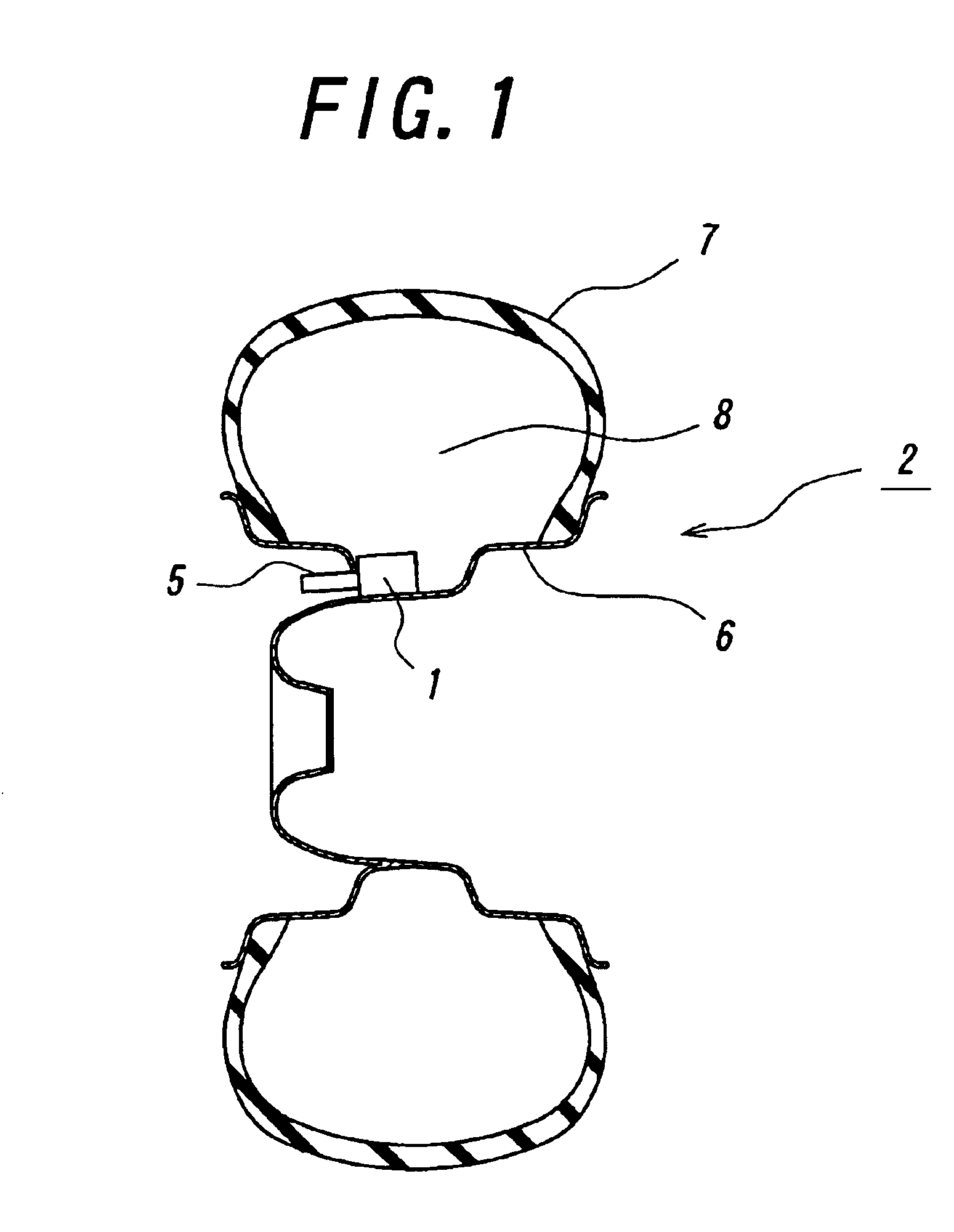
[0032]Hereinafter, inventive embodiments of the present invention will be described with reference to FIGS. 1 to 5. FIG. 1 is a schematic diagram showing in the state where a sensor unit 1 is installed in a tire wheel 2. The sensor unit 1 is coupled with a cylindrical valve device 5 for introducing air to be installed in a wheel rim 6. The wheel rim 6 and a tire 7 form a tire pressure part 8 and also constitute the tire wheel 2.

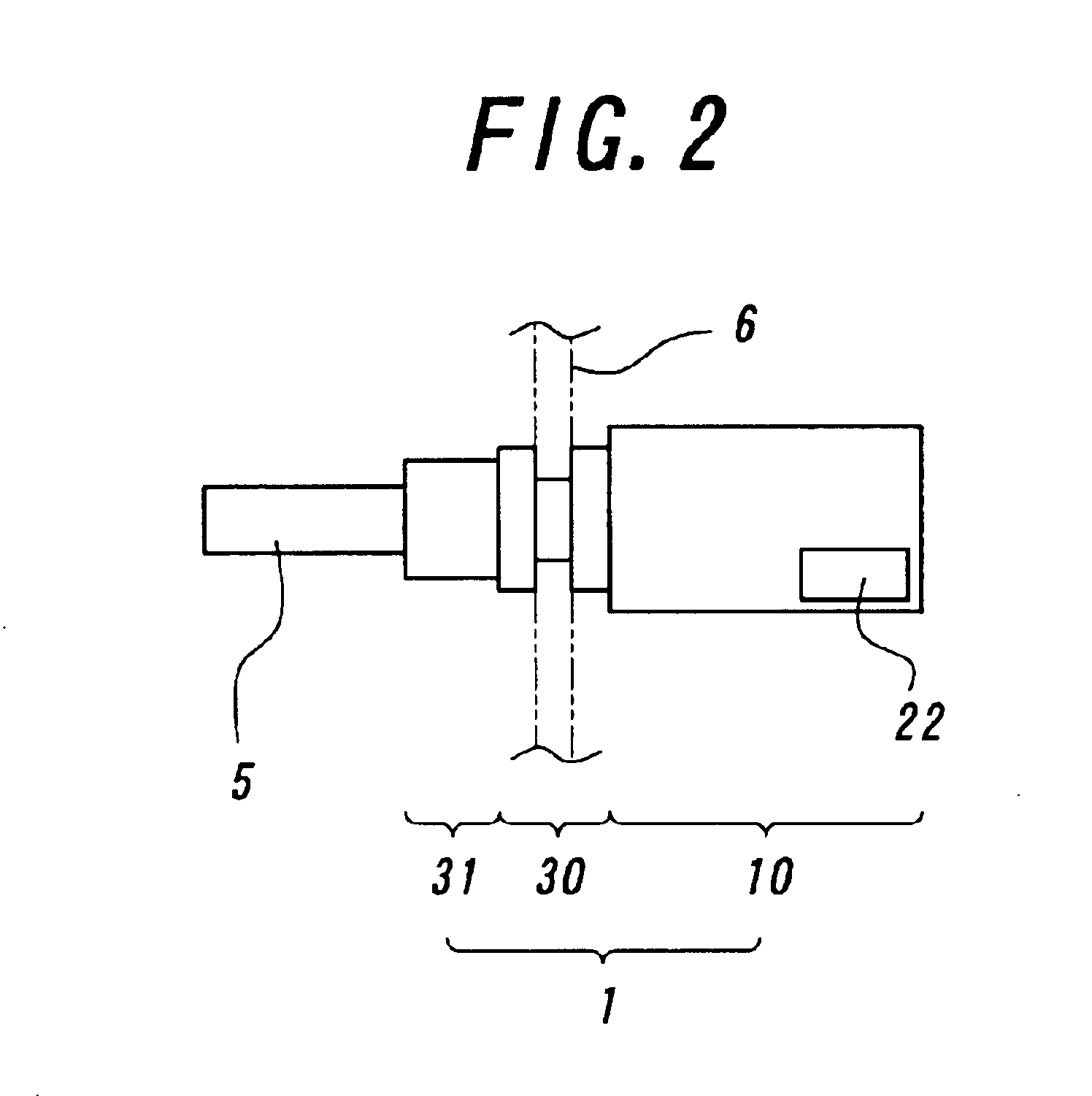
[0033]FIG. 2 is an outline diagram showing an outline of the sensor unit. The tire pressure sensor unit 1 is composed of a sensor unit body 10 having a external signal-importing terminal 22 for importing signals from external sources, a rim-attaching part 30 and an antenna part 31. The sensor unit 1 is also coupled with the valve device 5 to be installed in the wheel rim 6.

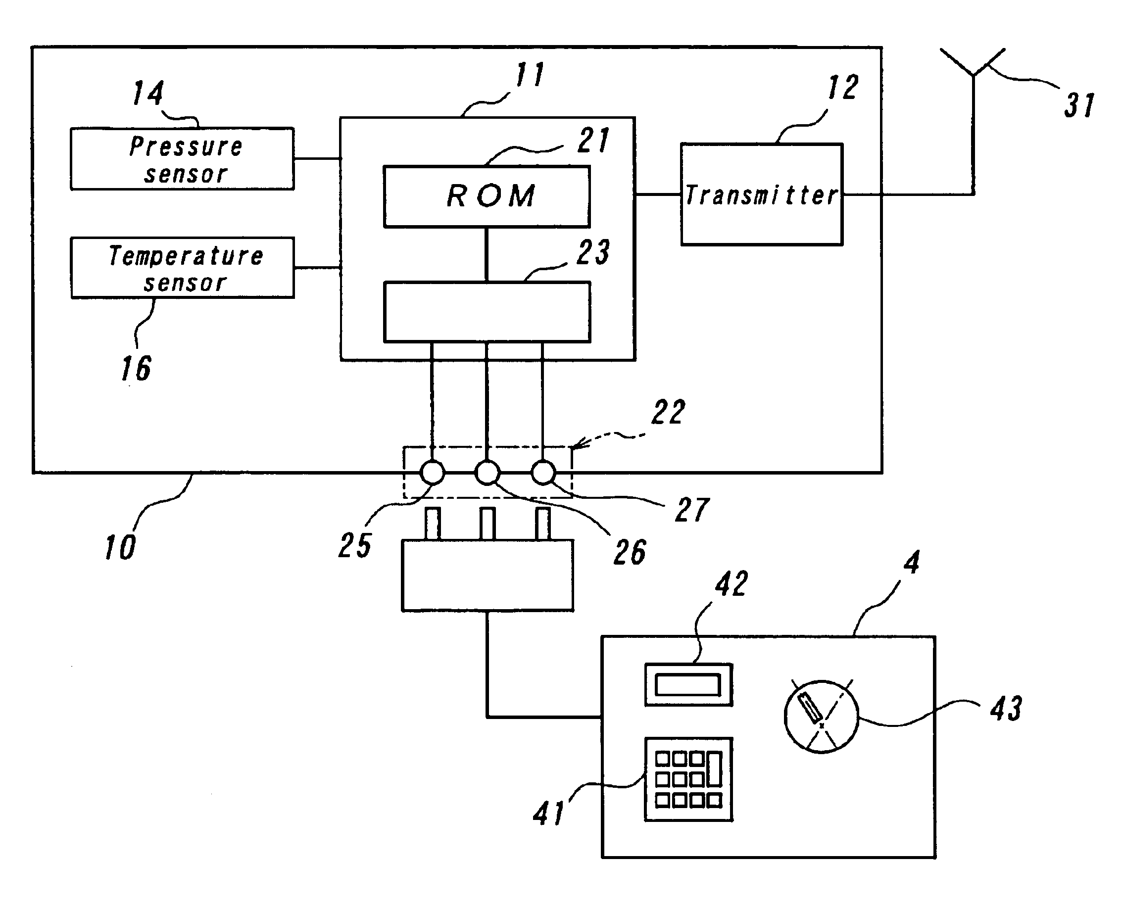
[0034]The sensor unit body 10 incorporates an electric circuit device shown in FIG. 3 as a schematic block diagram. The electric circuit device is composed of a pressure sensor 14 for detec...


PUM


Abstract

A sensor unit body 10 of a tire pressure sensor unit 1 is provided with external signal-importing terminals 22 for rewriting data of self-identification code stored in a ROM 21, so that a complex operation of associating the self-identification code of the sensor unit with its mounting position in the vehicle is eliminated by rewriting the self-identification code of the sensor unit 1 after the replacement to be identical to the self-identification code of the sensor unit 1 before the replacement, when a tire wheel is replaced due to a breakdown of the tire unit or a replacement between a summer tire and a winter tire.

Description

TECHNICAL FIELD[0001]The present invention relates to a tire pressure sensor unit for monitoring tire pressure of a vehicle and notifying a driver of a trouble (hereinafter referred to as the “sensor unit”), a tire pressure monitoring system using same, and a method of registering a self-identification code of the tire pressure sensor unit.BACKGROUND[0002]There has conventionally been known a tire pressure monitoring system having a tire pressure monitor provided on a vehicle body for notifying a driver of a trouble in tire pressure, and a sensor unit installed in a tire wheel of the vehicle for sensing pressure of a tire and transmitting information about the sensed tire pressure to the tire pressure monitor via radio waves.[0003]There has also been proposed a system in which, in order to notify the driver of information about a mounting position in the vehicle of the sensor unit detecting a trouble of the tire, for example, the right front wheel of the vehicle as well as the tire ...

Claims


Application Information

Patent Timeline
IPC IPC(8): B60C23/04B60C23/02
CPCB60C23/0416B60C23/0479
Inventor TOYOFUKU, MASANOBU
Owner BRIDGESTONE CORP
Why Eureka
Try Eureka