
Method and apparatus for parasitic load compensation

a technology of parasitic load and compensation method, which is applied in the direction of machines/engines, electrical control, instruments, etc., can solve the problems of inability to accurately determine the amount of power that the engine must generate, and the inability to accurately determine the net power output of a particular engin

Inactive Publication Date: 2005-07-19
CATERPILLAR INC
View PDF42 Cites 28 Cited by
  • Summary
  • Abstract
  • Description
  • Claims
  • Application Information

AI Technical Summary

Benefits of technology

[0008]In another aspect of the present invention, a method is disclosed for determining the net power output of an engine associated with a work machine or other vehicle wherein the work machine or other vehicle includes an engine operable to provide power to at least two power-operated components, at least one of the power-operated components being a parasitic load component. The present method includes coupling an electronic controller to the engine, sensing at least one engine parameter representative of the operating condition of the engine, determining the total output power of the engine...

Problems solved by technology

Since the engine controller does not typically know the nature and level of the parasitic loads being imposed upon the engine during a particular work task, the net power output of the engine broadcasted by the engine controller is deficient; it does not compensate for all parasitic load operation; and it does not yield an accurate determination of the amount of power that the engine must generate at any particular point in time.
Accurately determining the net power output of a particular engine is likewise complicated due to the fact that many manufacturers purchase the basic engine separate and apart from the various parasitic load components which will be added later to the completed work machine or other vehicle.
Since the engine manufacturers do not know what type of parasitic loads will be associated with a particular engine and, as a result, do not know the particular power requirements associated with such parasitic loads, they cannot program the associated engine controller to compensate for the wide variety of different power requirements associated with the operation of a wide variety of different parasitic loads when determining the net power output of the engine.
This mating of the engine with the vehicle chassis and its associated parasitic load components exemplifies the difficulty in accurately compensating for the power requirements associated with any parasitic load encountered during a particular work task.

Method used


Image

  • Method and apparatus for parasitic load compensation
  • Method and apparatus for parasitic load compensation
  • Method and apparatus for parasitic load compensation

Examples


Embodiment Construction

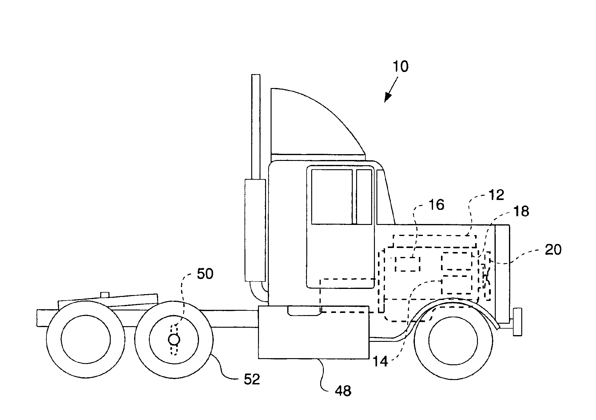
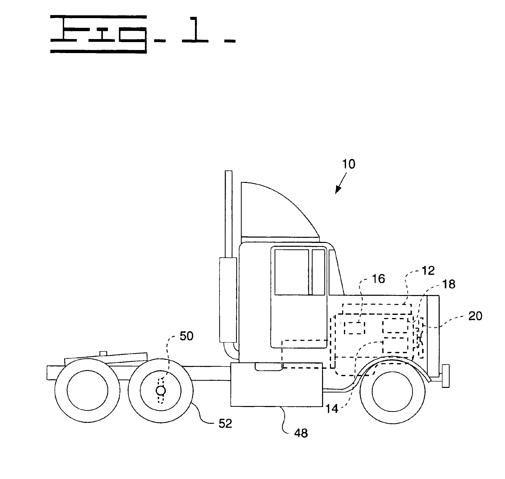
[0015]Referring to FIG. 1, numeral 10 in FIG. 1 represents a typical truck chassis having an engine 12 associated therewith including some typical peripheral devices or parasitic load components such as, for example, an air conditioning compressor 14, an alternator 16, a hydraulic pump 18, and a cooling fan 20. As illustrated in FIG. 1, the engine 12 associated with the particular truck chassis 10 is used to drive such vehicle as well as the other systems associated therewith including still other parasitic load components. In this regard, it is recognized that a typical vehicle manufacturer will collect and gather all of the necessary components associated with the construction and operation of a particular vehicle or work machine such as the chassis 10, engine 12, and parasitic load devices 14-20 illustrated in FIG. 1 and thereafter assemble the same onto the vehicle chassis during the construction and assembly process. It is also recognized and anticipated that the various parasi...


PUM


Abstract

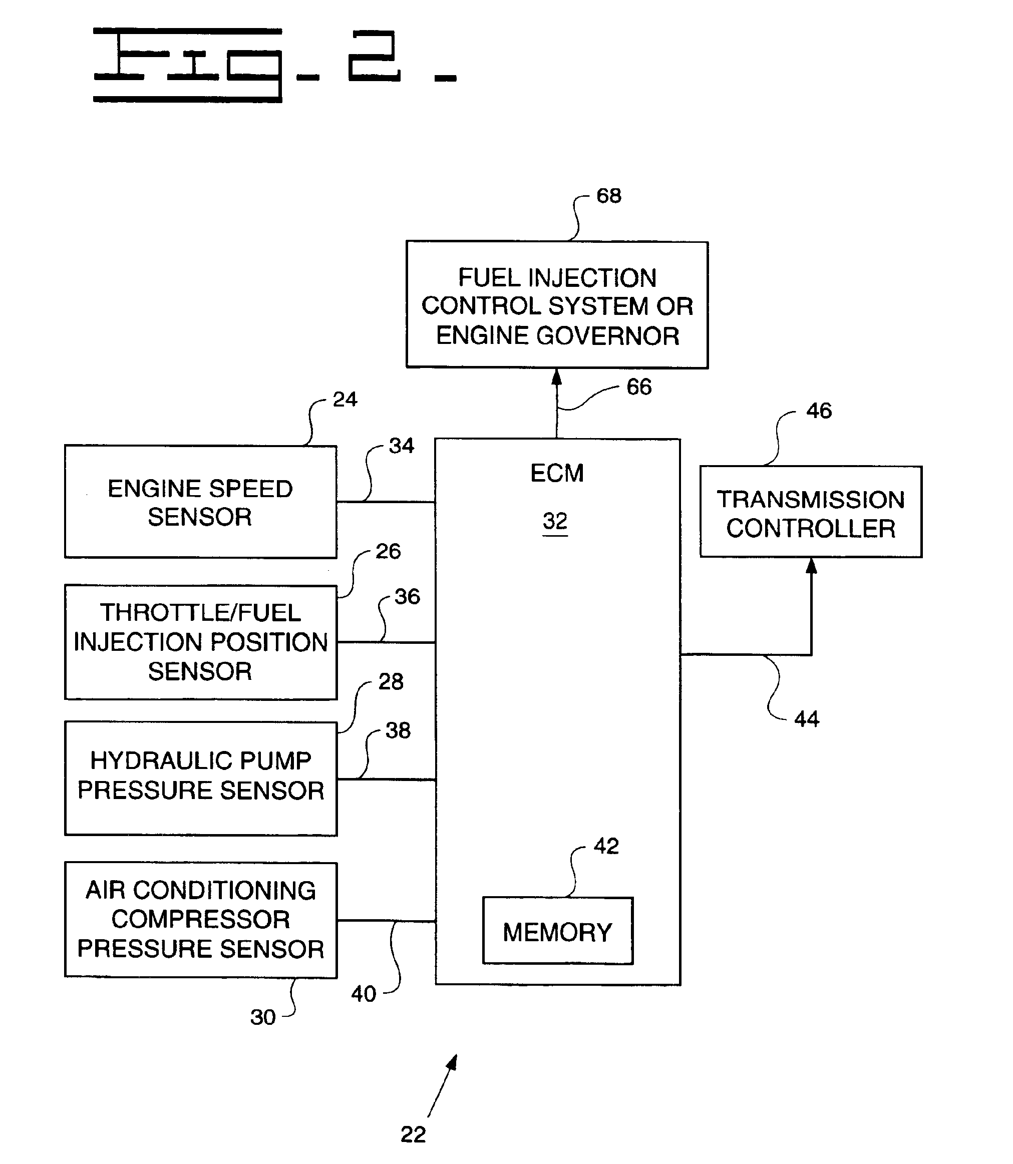
A control system for determining the net power output of an engine associated with a work machine or other vehicle wherein parasitic loads encountered during engine operation are taken into account, the control system including an electronic controller coupled to the engine, at least one sensor coupled to the controller for inputting at least one signal representative of certain operating parameters associated with the engine, and at least one other sensor coupled to the controller for inputting at least one signal representative of the operation of any parasitic load encountered during engine operation, the controller being operable to determine the total output power of the engine and the power requirements associated with any parasitic load based upon the sensor signals. The controller is also operable to output a signal representative of the difference between the total output power of the engine and the power requirements associated with any parasitic loads encountered during engine operation, the outputted signal being used for controlling the operation of the engine or other peripheral equipment or systems associated with the work machine or other vehicle.

Description

TECHNICAL FIELD[0001]This invention relates generally to systems for monitoring and determining the power output of an engine and, more particularly, to a method and apparatus for more accurately determining the net power output of an engine associated with a work machine or other vehicle by automatically compensating for any parasitic loads encountered during engine operation.BACKGROUND[0002]Engines associated with work machines such as earthmoving and excavating equipment as well as over the road and off-road vehicles not only provide motive force for the particular work machine or other vehicle but such engines also power peripheral devices such as hydraulic pumps, cooling fans, compressors, air conditioners, generators (alternators) and other parasitic load components. Depending upon the particular work machine or other vehicle, the engine may be operated at a substantially constant speed or at variable speeds where instantaneous changes in output power are needed. In a similar ...

Claims


Application Information

Patent Timeline
IPC IPC(8): F02D41/08
CPCF02D41/083F02D2200/1006F02D2250/18
Inventor LANDES, JAMES W.RETTIG, MARK E.
Owner CATERPILLAR INC
Learn More