Valve drive unit and series thereof

a technology of drive unit and valve body, which is applied in the direction of valve body gearing, valve operating means/release devices, transportation and packaging, etc., can solve the problems of low rotation efficiency, high power consumption of the drive unit, and weak drive unit against the load put on the valve body, so as to reduce costs and reduce the burden of stock

Inactive Publication Date: 2005-07-19
SUMITOMO HEAVY IND LTD
View PDF9 Cites 8 Cited by
  • Summary
  • Abstract
  • Description
  • Claims
  • Application Information

AI Technical Summary

Benefits of technology

[0008]The present invention is in view of the problems described above. An object of the present invention is to provide a valve drive unit and a series thereof, which can set up proper rotational efficiency and anti-counter-rotating function of the valve body in accordance with a use application, with realizing miniaturization and space savings of the driver units.
[0011]In other words, the high torque is needed when the valve body starts rotating from a stop condition. Conversely, even if a certain level of load is put on the valve body, the drive unit can have high anti-counter-rotating effect due to strong holding power. Also the valve body can be rotated with the low torque after the startup of the valve body (during the rotation), so that it is possible to increase the rotational efficiency of the valve body and to decrease the power consumption of the motor.
[0012]Furthermore, structure of the valve drive unit can make difference in eccentric rotational resistance of the external gear, so that it is possible to provide a plurality of valve drive units, in which set up as to the rotational efficiency and the anti-counter-rotating function of the valve body in accordance with a use application is carried out by small design change.
[0016]In order to easily make the difference in the eccentric wobbling rotational resistance of the external gear, the eccentric wobbling inscribed gear type of the planetary gear mechanism has an eccentric element to wobbly rotates the external gear and various sliding conditions are brought about in a sliding section between the eccentric element and the external gear. Alternatively, the carrier includes an inner pin which is fitted into an inner pinhole formed in the external gear with play to absorb the wobbling ingredient of the external gear, and various sliding conditions are brought about in a sliding section between the inner pinhole and the inner pin. Then, it is possible to adjust smoothness of rotation and the anti-counter-rotating function of the valve body.
[0018]If components, except for a component to make the difference in the eccentric wobbling rotational resistance of the external gear, are shared (used commonly) among the series of valve drive units, almost all components are practically shareable. Therefore, it is possible to reduce costs, a burden of stock and the like.

Problems solved by technology

The drive unit, however, has low rotational efficiency during the rotating operation (especially at a start of rotation,) so that there is a problem that the drive unit needs high power consumption in a case where the drive unit is frequently actuated by a motor.
However, there is another problem that the drive unit is weak against the load put on the valve body because of its structure easy to rotate in reverse.

Method used


Image

  • Valve drive unit and series thereof
  • Valve drive unit and series thereof
  • Valve drive unit and series thereof

Examples


Embodiment Construction

[0025]An embodiment of the present invention will be hereinafter described with reference to the drawings.

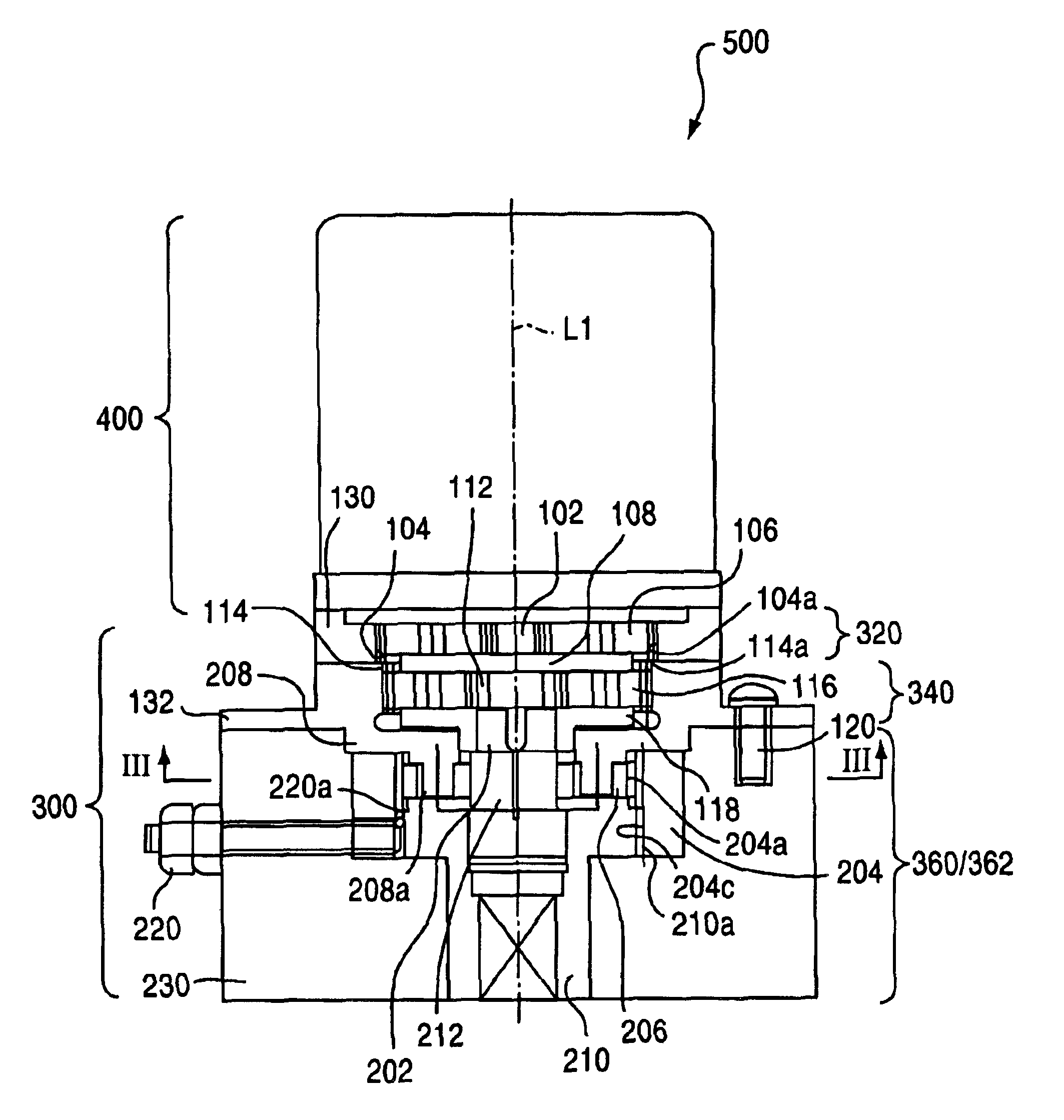
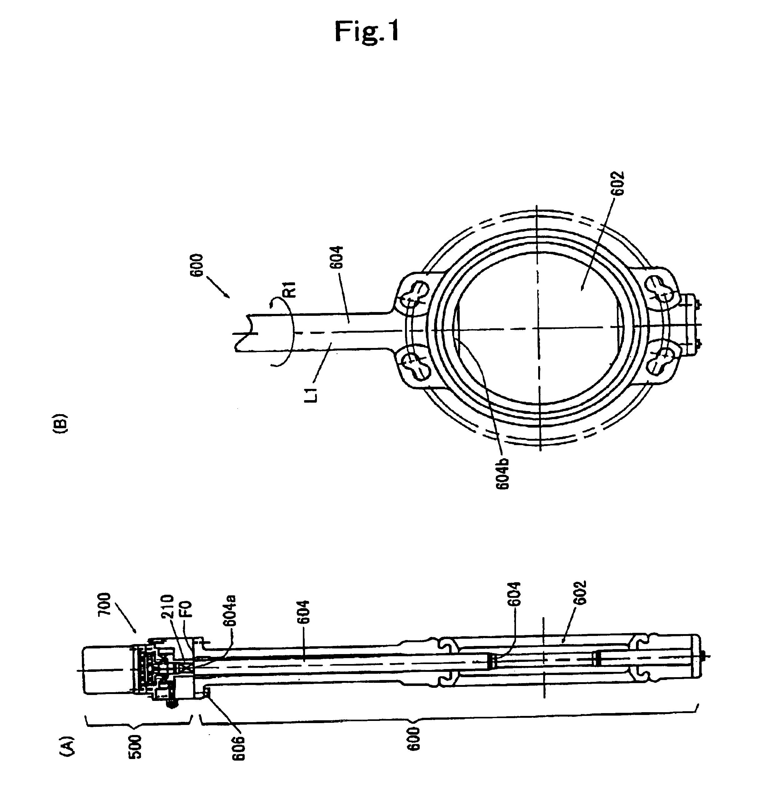
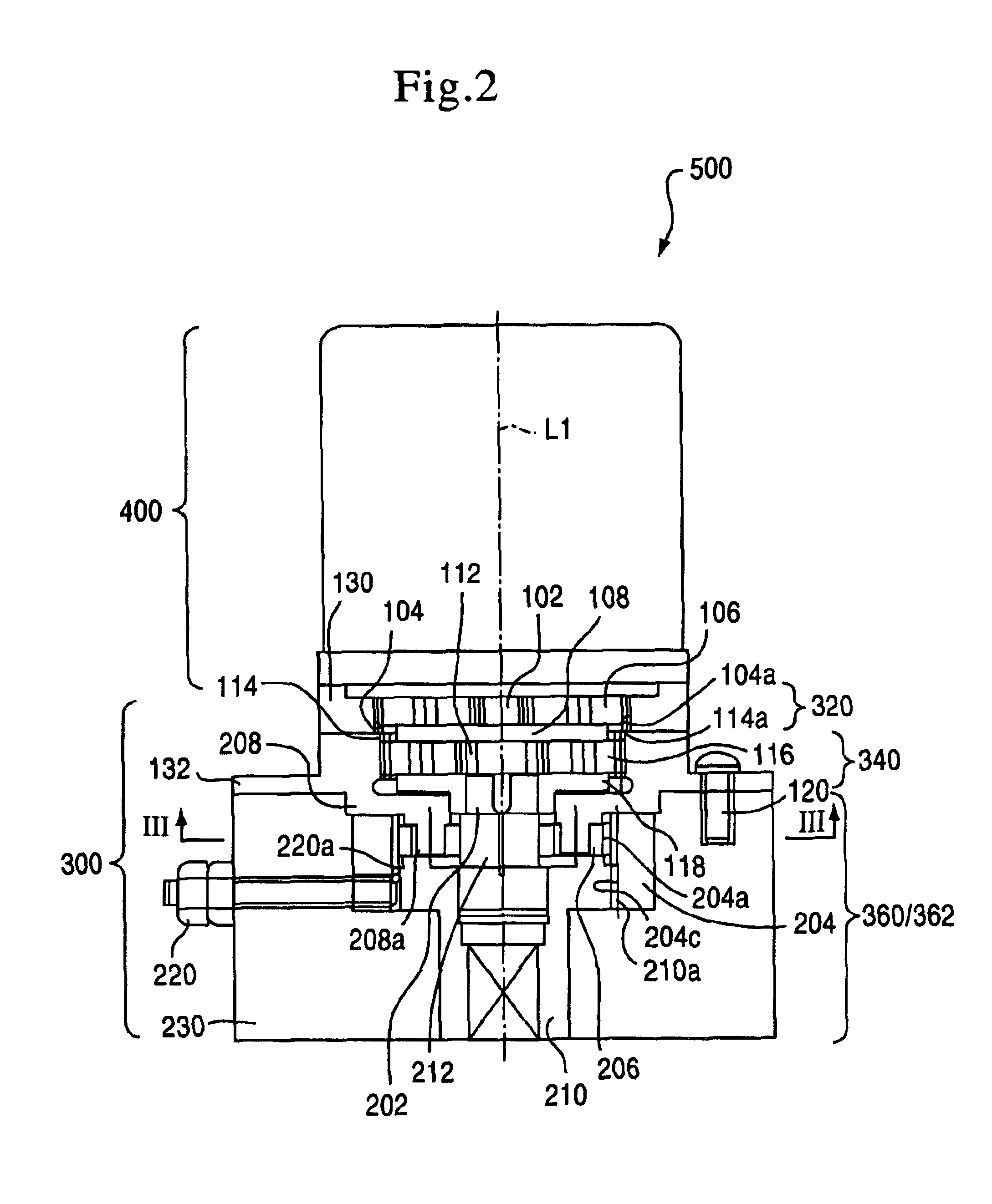
[0026]FIG. 1A is a sectional side view of a motor-operated valve 700 in which an electric valve drive unit 500 in a series (a product group) of valve units according to the present invention is used for rotating a rotary valve 600 (a butterfly valve in this embodiment). FIG. 1B is a front view in the vicinity of a valve body 602 of the rotary valve 600.

[0027]The motor-operated valve 700 includes the electric valve drive unit 500 and the rotary valve 600.

[0028]The rotary valve 600, which mainly includes the valve body 602 and a valve shaft 604, is integrally secured to the electric valve drive unit 500 described later with a bolt 606 with bordering on a fixing surface F0. A dimension of the fixing surface F0 adheres to an ISO flange dimension so as to have compatibility with other rotary valves.

[0029]Since one end 604a of the valve shaft 604 (an upper side in FIG. 1) is secured t...


PUM


Abstract

A series of electric valve drive units is provided, which can set up rotational efficiency and anti-counter-rotating function of a valve. In a series of electric valve drive units which can drive a valve body via reduction gears, at least one gear mechanism of the reduction gears is provided with an eccentric wobbling inscribed gear type of a planetary gear mechanism which has an input shaft, an external gear eccentrically and wobbly rotating about the input shaft, an internal gear engaged with the external gear, and a carrier absorbing a wobbling ingredient of the external gear. At least two types of valve drive units are supplied, one of which places prime importance on the anti-counter-rotating function, and the other places prime importance on the rotational efficiency.

Description

BACKGROUND OF THE INVENTION[0001]1. Field of the Invention[0002]The present invention relates to a drive unit of a valve body such as a ball valve, a butterfly valve and the like, and particularly relates to a series (a product group) of valve drive units which can drive the valve body via reduction gears.[0003]2. Description of the Prior Art[0004]A valve unit having a ball valve, a butterfly valve, or the like is generally known. The valve unit is disposed in a pipe of building materials, a sewage drain, for example, to open and close a duct and to adjust the quantity of flow. To drive these valve units, various types of manual or electric valve drive units are suggested. Japanese Patent No. 3054540, for example, discloses a valve drive unit employing a worm gear mechanism which is the most commonly used. In addition to the drive unit with the worm gear mechanism, a drive unit with a simple planetary gear mechanism is suggested to realize space savings.[0005]These drive units have ...

Claims


Application Information

Patent Timeline
IPC IPC(8): F16K31/04F16K31/53F16H1/28F16H1/32
CPCF16K31/048Y10T74/19014Y10T137/5109F16K31/53
Inventor MINEGISHI, KIYOJITAMENAGA, JUN
Owner SUMITOMO HEAVY IND LTD
Why Eureka
Try Eureka