
Detecting network instability

a network instability and detection technology, applied in the field of monitoring network devices, can solve problems such as data being discarded or lost, devices processing packets at a slower rate or even crash, and devices receiving an inordinate amount of packets to be processed exceeding their processing capacity

Inactive Publication Date: 2005-07-12
IBM CORP
View PDF19 Cites 29 Cited by
  • Summary
  • Abstract
  • Description
  • Claims
  • Application Information

AI Technical Summary

Benefits of technology

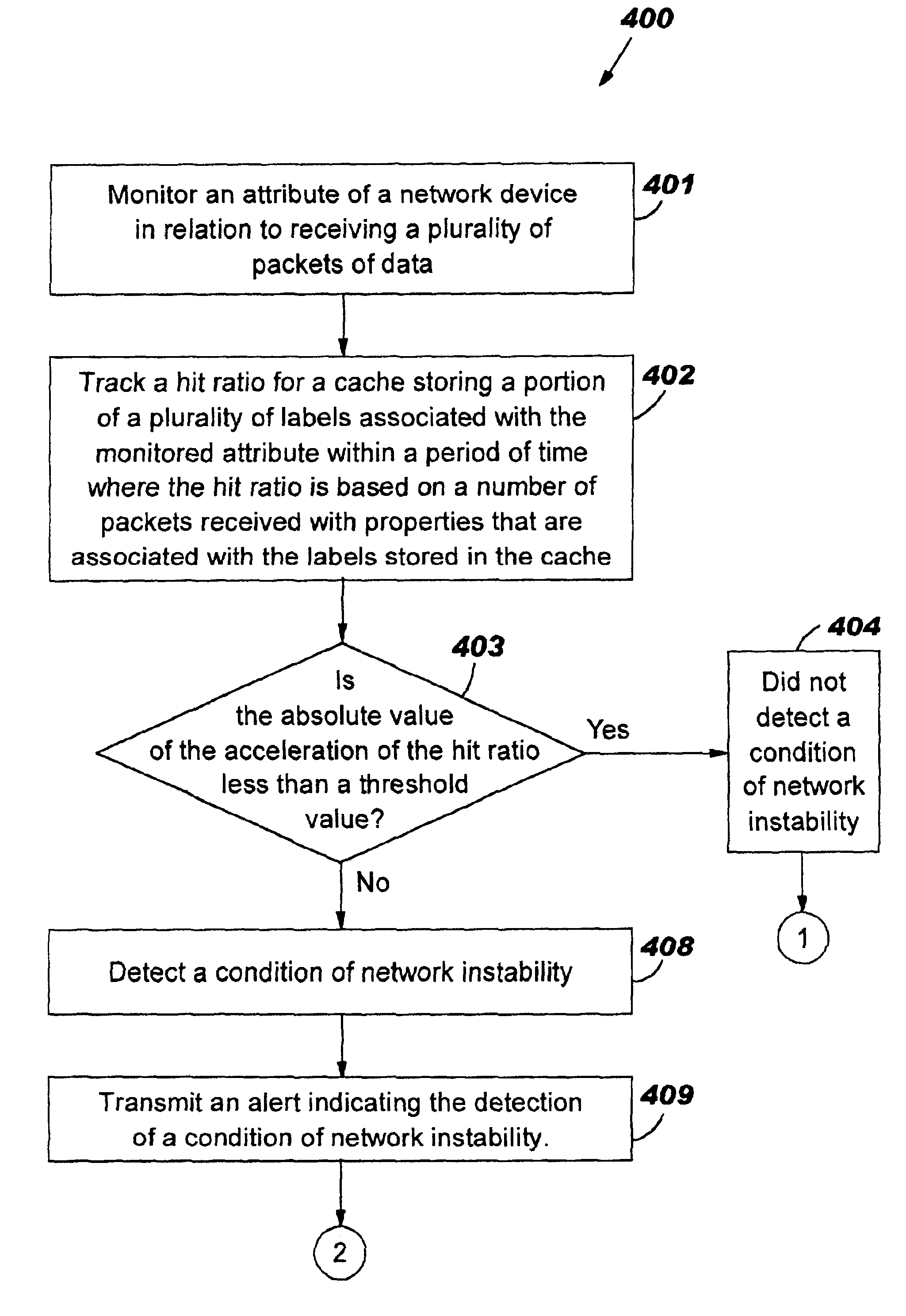
[0007]The problems outlined above may at least in part be solved in some embodiments by monitoring an attribute, e.g., processor and / or co-processor utilization, packet arrival rates, packet peak rates, packet size distribution, packet clustering tendencies, buffer usage patterns, occurrence of peak utilization, out-of-buffer conditions, packet discard rates, of a network device, e.g., router, indicative of network instability. The attribute may be associated with a plurality of labels (variables) where a portion of those labels may be stored in a cache. A hit ratio for the cache storing labels associated with the monitored attribute may be tracked within a period of time based on the number of requested labels that are stored in the cache. A condition of network instability may then be detected based on the hit ratio. For example, if the absolute value of the acceleration of the hit ratio exceeds a threshold, then a condition of network instability may be detected. That is, an accelerated change in the hit ratio may indicate an unstable condition.

Problems solved by technology

However, during periods of network instability, data may be discarded or lost due to hardware or software failures.
Network instability may refer to abnormal situations that cause a device in the network to become overloaded thereby causing the device to process packets at a slower rate or even crash.
For example, the device may receive an inordinate amount of packets to be processed exceeding its processing capability.
In another example, the device may receive an inordinate amount of requests to be serviced such as in a denial-of-service attack that exceeds the processing capacity of the device.
Typically, network instability situations that cause one or more network devices to become overloaded do not become detected until well after the loss or discarding of data.
If, however, a parameter that indicates network instability situations was monitored, then a network instability situation may be detected prior to the instability situation significantly affecting the network.
For example, if the absolute value of the acceleration of the hit ratio exceeds a threshold, then a condition of network instability may be detected.
That is, an accelerated change in the hit ratio may indicate an unstable condition.
However, if the next label, e.g., label “G”, is not present in the cache, then a “cache miss” is said to occur.
That is, if there is not an accelerated change in the hit ratio of a cache storing labels associated with a monitored attribute indicative of network instability, then the network device did not detect a condition of network instability.
That is, an accelerated change in the hit ratio may indicate an unstable condition.
For example, an accelerated change in the hit ratio indicating an influx in the number of received packets may indicate receipt of an unusually high number of packets, i.e., high packet peak rates, which may cause the network device to become overloaded thereby causing the network device to process packets at a slower rate or even crash.
Hence, detecting an accelerated change in the hit ratio may detect a condition of network instability.
A detection of network instability may not be an administrative emergency and hence may be deemed to not be a valid condition of network instability.
Hence, the network administrator may deem the condition detected to not be a valid condition of network instability.
Hence, a more limited number of situations or conditions may be deemed to be indicative of network instability.

Method used


Image

  • Detecting network instability
  • Detecting network instability
  • Detecting network instability

Examples


Embodiment Construction

FIG. 1—Network System

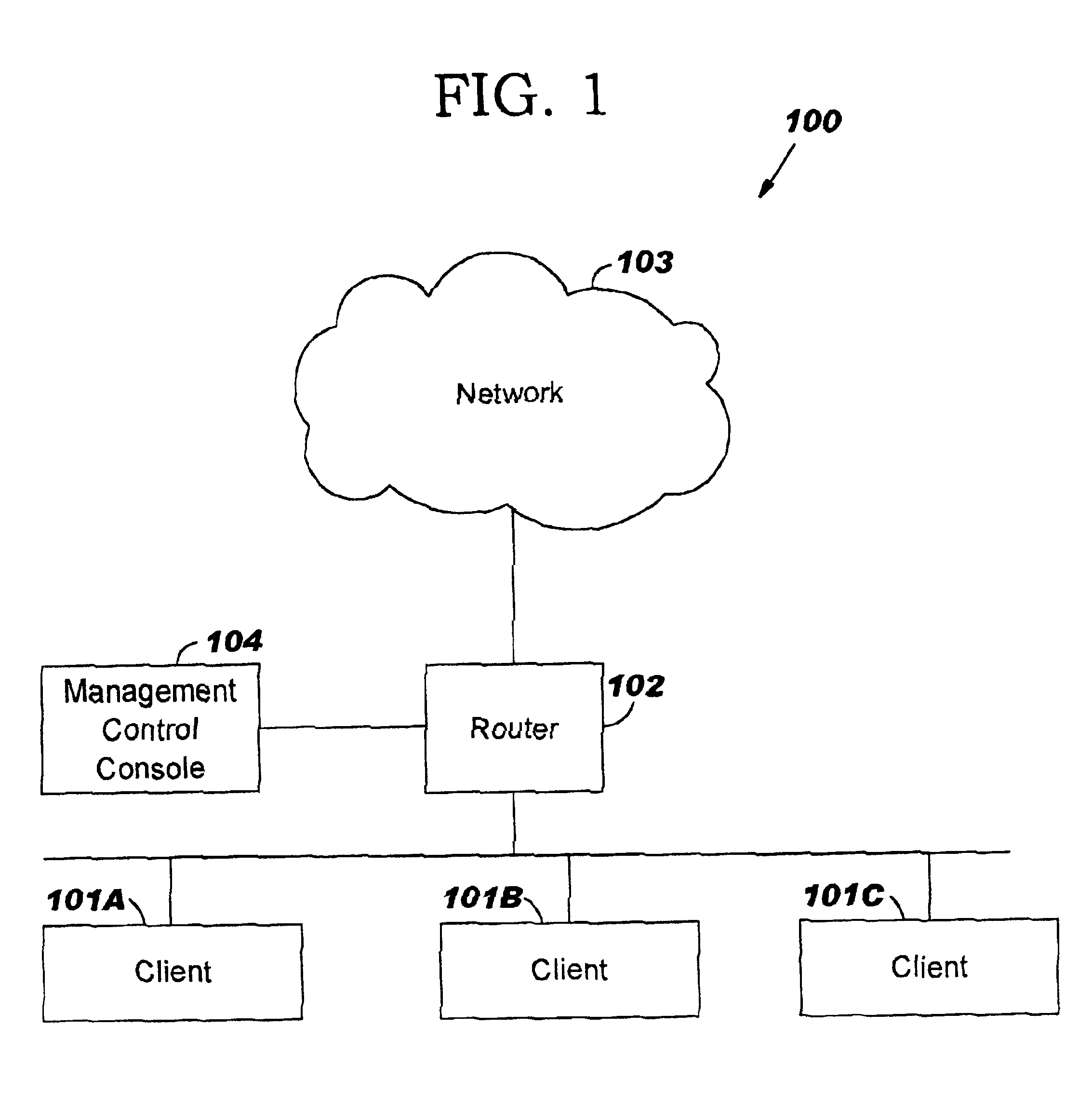
[0031]FIG. 1 illustrates an embodiment of a network system 100 in accordance with the present invention. Network system 100 may comprise one or more clients 101A-C coupled to a router 102. Clients 101A-C may collectively or individually be referred to as clients 101 or client 101, respectively. A more detailed description of client 101 is provided below in conjunction with FIG. 2. A more detailed description of router 102 is provided further below in conjunction with FIG. 3. Network system 100 may further comprise a network 103 coupled to router 102. Router 102 may be configured to forward packets of data issued from clients 101 to network 103. Network 103 may be a Local Area Network (LAN), e.g., Ethernet, Token Ring, ARCnet or a Wide Area Network (WAN), e.g., Internet. Network system 100 may further comprise a management control console 104 (also referred to as a central management station) coupled to router 102. It is noted that the connection between clients ...


PUM


Abstract

A method, system and computer program product for detecting conditions of network instability. An attribute indicative of network instability, e.g., processor and / or co-processor utilization, packet arrival rates, packet peak rates, packet size distribution, packet clustering tendencies, buffer usage patterns, occurrence of peak utilization, out-of-buffer conditions, packet discard rates, may be monitored for a network device, e.g., router. The monitored attribute may be associated with a plurality of labels (variables) where a portion of those labels may be stored in a cache. A hit ratio for the cache storing labels associated with the monitored attribute may be tracked within a period of time based on the number of requested items, i.e., labels, that are currently stored in the cache. A condition of network instability may then be detected based on the hit ratio by determining if the absolute value of the acceleration of the hit ratio exceeds a threshold.

Description

TECHNICAL FIELD[0001]The present invention relates to the field of monitoring network devices, and more particularly to detecting conditions of network instability based on the acceleration of the hit ratio of a particular attribute, e.g., packet arrival rates, buffer usage patterns, packet discard rates, out-of-buffer conditions, monitored.BACKGROUND INFORMATION[0002]A network generally includes a number of devices connected to allow inter-device communication. As the size of a network increases, it becomes increasingly important to effectively and efficiently monitor and manage the network. Typically, a site commonly referred to as a management control console (also known as a central management station) may communicate with an entity (commonly referred to as an agent) in a device, e.g., router, switch, in order to be able to monitor and manage that device. The management control console may be able to monitor and manage the device by obtaining and configuring various parameters. ...

Claims


Application Information

Patent Timeline
Patent Type & Authority Patents(United States)
IPC IPC(8): H04L12/26H04L12/24
CPCH04L41/0681H04L43/0829H04L43/0894H04L43/16
Inventor BARTUCCA, FRANCIS MICHAELJEFFRIES, CLARK DEBSSLAGER, ROSEMARY VENEMASTROLE, NORMAN CLARK
Owner IBM CORP
Learn More