
Network appliance that determines what processor to send a future packet to based on a predicted future arrival time

a network appliance and processor technology, applied in the field of network appliances, can solve the problems of limiting the performance of the network appliance, slow performance of deep packet inspection,

Active Publication Date: 2014-05-08
NETRONOME SYST
View PDF2 Cites 24 Cited by
  • Summary
  • Abstract
  • Description
  • Claims
  • Application Information

AI Technical Summary

Benefits of technology

[0003]A network appliance includes a flow processor and a plurality of processing units. A processing unit may, for example, be a processor integrated circuit that has a CPU (Central Processing Unit) and cache memory. Alternatively, a processing unit may be several integrated circuits that together include a processor and associated cache memory. Regardless of how the processing unit is realized, packets of numerous flows pass through the network appliance. For example, a flow pair may involve a first flow of packets and a second flow of packets. The first flow passes from a first network device, to the network appliance, through the network appliance, and to a second network device. The second flow passes in the opposite direction from the second network device, to the network appliance, through the network appliance, and to the first network device. The layer 4 protocol of the packets of the two flows is TCP (Transmission Control Protocol) and the two flows together realize a TCP connection between the first network device and the second network device. There are many such flow pairs, the packets of which pass through the network appliance on their ways between various network devices. The network appliance may simply route the packets, or the network appliance may route the packets and perform other functions. The network appliance may perform metering, monitoring, policing, and other functions.

Problems solved by technology

Performing this deep packet inspection is slow and may limit the performance of the network appliance, but knowing the application protocol type is often necessary in order to otherwise optimize performance of the network appliance.

Method used


Image

  • Network appliance that determines what processor to send a future packet to based on a predicted future arrival time
  • Network appliance that determines what processor to send a future packet to based on a predicted future arrival time
  • Network appliance that determines what processor to send a future packet to based on a predicted future arrival time

Examples


Embodiment Construction

[0014]Reference will now be made in detail to some embodiments of the invention, examples of which are illustrated in the accompanying drawings.

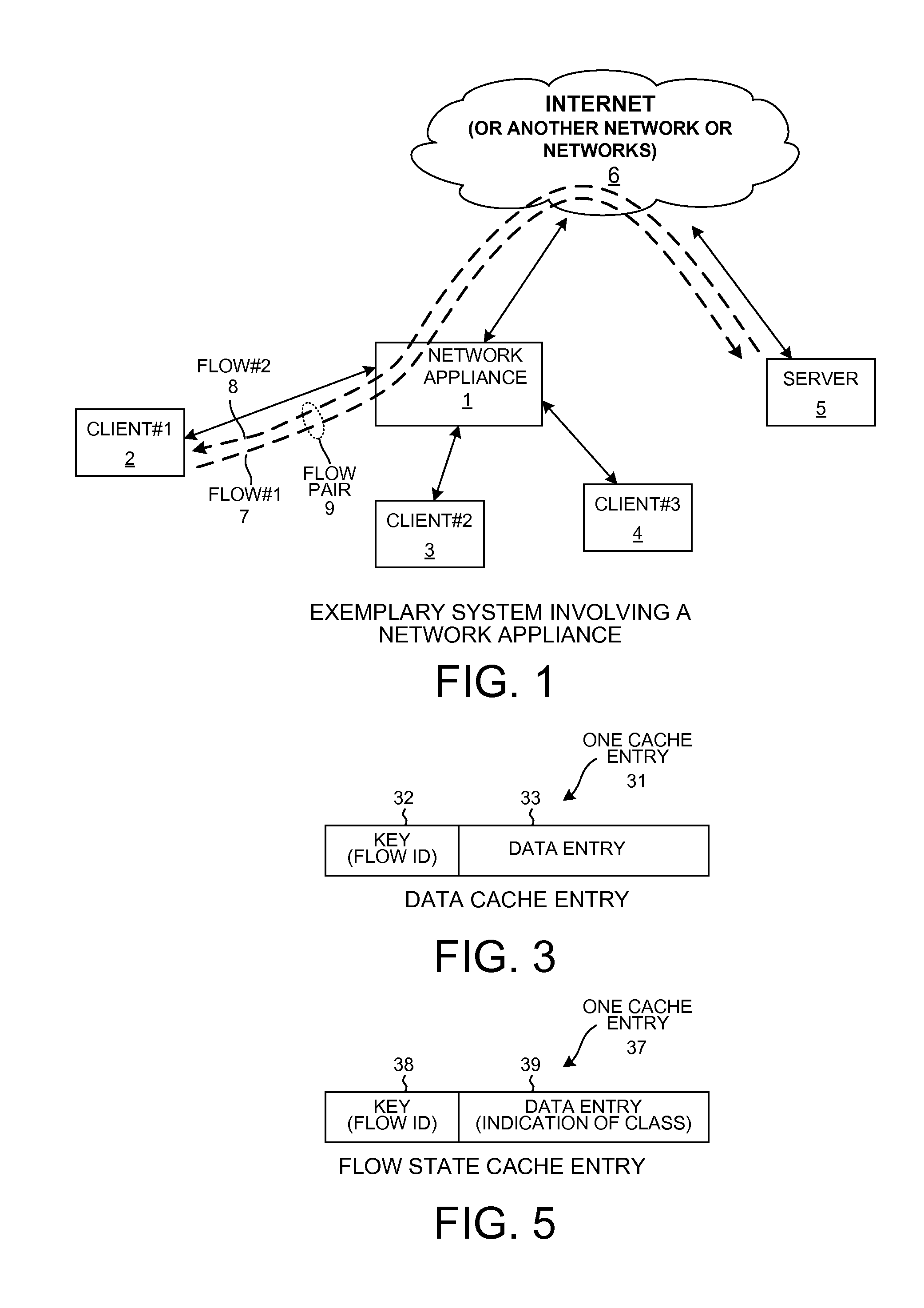
[0015]FIG. 1 is a simplified diagram of a system employing a network appliance 1 in accordance with one novel aspect. Network appliance 1 is in network communication with numerous client network devices 2, 3 and 4 as well as with a server 5. Communication with the server 5 in the illustrated example is through a network or networks. In one example, the networks are the Internet 6 as illustrated in FIG. 1. The various clients 2-4 and the server 5 can communicate data back and forth between each other using the TCP / IP protocol suite. In the illustrated example, client 2 is in TCP / IP communication with server 5. Client 2 sends a first flow 7 of TCP / IP packets to server 5 through network appliance 1 and Internet 6. Server 5 sends a second flow 8 of TCP / IP packets to client 2 through Internet 6 and network appliance 1. The term “flow” as it is us...


PUM


Abstract

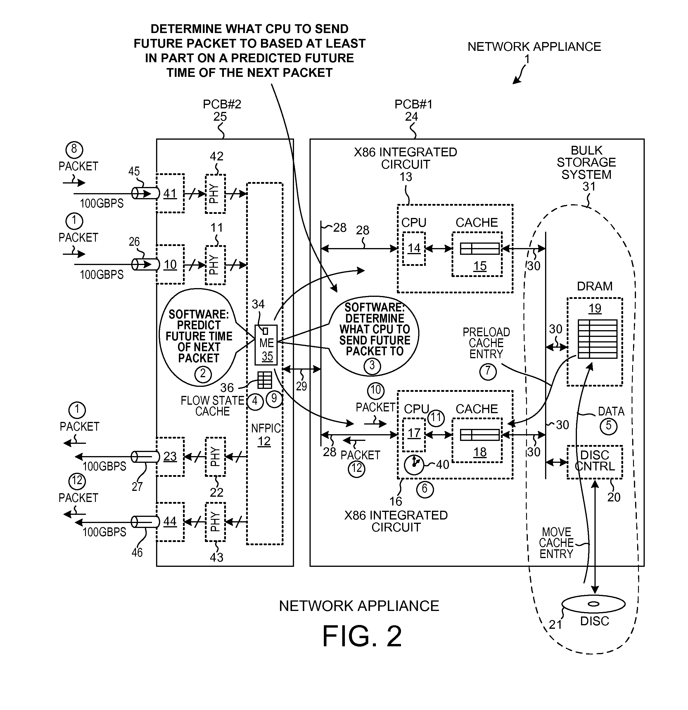
A network appliance includes a network processor and several processing units. Packets a flow pair are received onto the network appliance. Without performing deep packet inspection on any packet of the flow pair, the network processor analyzes the flows, estimates therefrom the application protocol used, and determines a predicted future time when the next packet will likely be received. The network processor determines to send the next packet to a selected one of the processing units based in part on the predicted future time. In some cases, the network processor causes a cache of the selected processing unit to be preloaded shortly before the predicted future time. When the next packet is actually received, the packet is directed to the selected processing unit. In this way, packets are directed to processing units within the network appliance based on predicted future packet arrival times without the use of deep packet inspection.

Description

TECHNICAL FIELD[0001]The described embodiments relate generally to network appliances that communicate flows of packets.BACKGROUND INFORMATION[0002]There are several types of network appliances that communicate flows of packets. In one example, the network appliance is a switch or router through which a plurality of client network devices interconnect to the Internet. A great many different flows, which may be as many as one million flows, may pass through such a network appliance. In order to be able to direct packets of these many flows in various ways within the network appliance in an efficient manner, the network appliance must generally determine the application protocol type of the packets of each flow. Accordingly, the network appliance performs deep packet inspection on a packet of each flow and thereby determines various things about the flow, including the application protocol type of the flow. Performing this deep packet inspection is slow and may limit the performance o...

Claims


Application Information

Patent Timeline
Patent Type & Authority Applications(United States)
IPC IPC(8): H04L12/56
CPCH04L43/00H04L45/30H04L43/0852H04L47/283H04L47/245
Inventor STARK, GAVIN J.VILJOEN, NICOLAAS J.VILJOEN, NIELNEUGEBAUER, ROLF
Owner NETRONOME SYST
Learn More