Load driver and control method for safely driving DC load and computer-readable recording medium with program recorded thereon for allowing computer to execute the control
a technology of dc load and computer-readable recording medium, which is applied in the direction of motor/generator/converter stopper, dynamo-electric converter control, dynamo-electric gear control, etc., can solve the problems of overvoltage applied to dc/dc converter, inability to reduce the overall cost, and significant requirements for components specification, etc., to achieve safe driving
- Summary
- Abstract
- Description
- Claims
- Application Information
AI Technical Summary
Benefits of technology
Problems solved by technology
Method used
Image
Examples
first embodiment
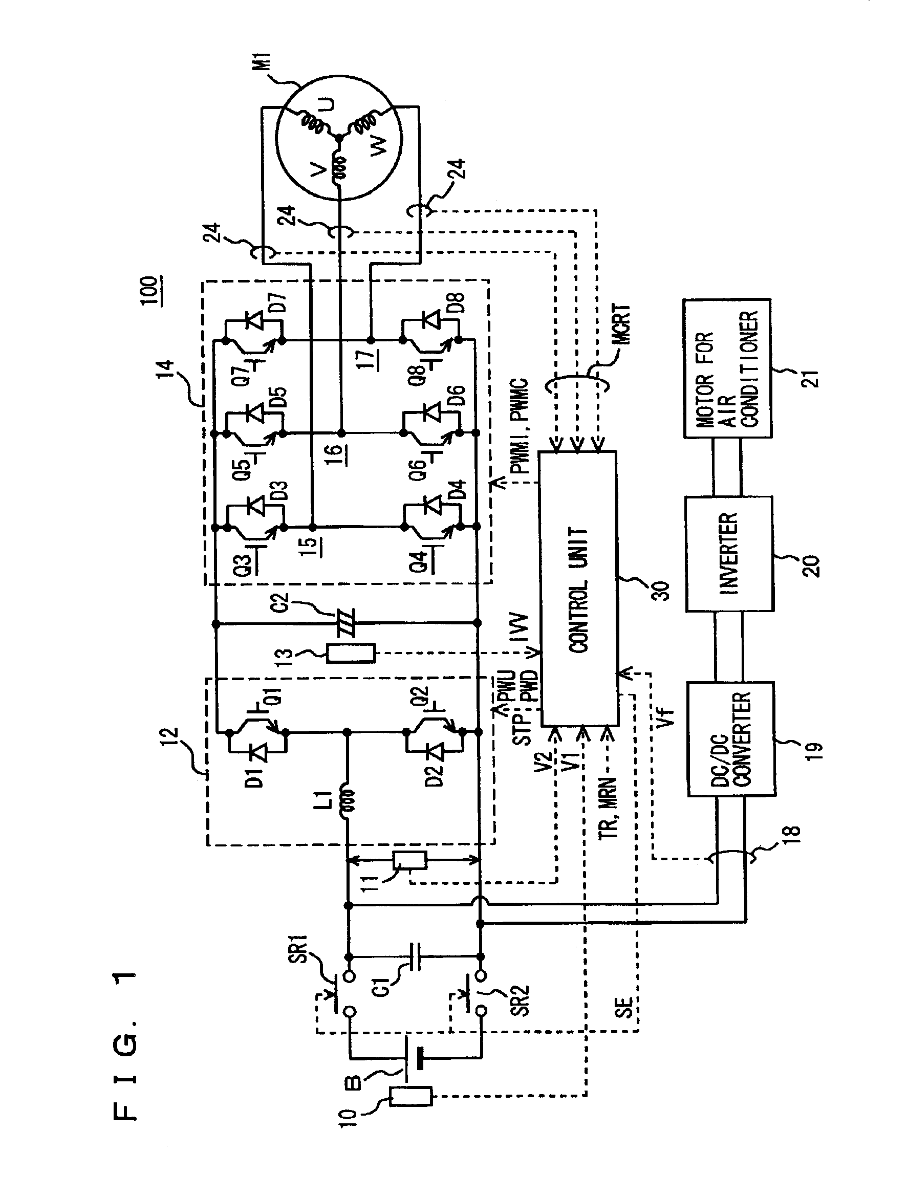
[0085]Referring to FIG. 1, a motor driver 100 having a load driver according to a first embodiment of the present invention includes a DC power supply B, voltage sensors 10, 11, 13 and 18, system relays SR1 and SR2, capacitors C1 and C2, an up-converter 12, an inverter 14, a current sensor 24, and a control unit 30. Motor driver 100 drives one motor M1. Motor M1 is a drive motor generating torque for driving drive wheels of a hybrid or electric vehicle. This motor serves as a power generator driven by an engine as well as an electric motor for the engine. Alternatively, the motor may be capable of starting the engine and incorporated as such into a hybrid vehicle.
[0086]Up-converter 12 includes a reactor L1, NPN transistors Q1 and Q2 and diodes D1 and D2. Reactor L1 has one end connected to a power supply line of DC power supply B and the other end connected to the intermediate point between NPN transistors Q1 and Q2, i.e., between the emitter of NPN transistor Q1 and the collector o...
second embodiment
[0149]Referring to FIG. 7, a motor driver 200 having a load driver according to a second embodiment includes a DC power supply B, voltage sensors 10, 11, 13 and 18, system relays SR1 and SR2, capacitors C1 and C2, an up-converter 12, inverters 14 and 31, current sensors 24 and 28, and a control unit 300. Motor driver 200 drives two motors M1 and M2. Of the motors M1 and M2, one motor M1 generates torque for driving drive wheels of a hybrid or electric vehicle and the other motor M2 is used for a power generator or for auxiliary equipment if the vehicle is the hybrid vehicle and is used for auxiliary equipment if the vehicle is the electric vehicle.
[0150]DC power supply B, voltage sensors 10, 11, 13 and 18, system relays SR1 and SR2, capacitors C1 and C2, up-converter 12, inverter 14, and current sensor 24 are as those described above in connection with the first embodiment. Here, capacitor C2 receives a DC voltage from up-converter 12 via nodes N1 and N2 to smooth the received DC vo...
PUM
 Abstract
Description
Claims
Application Information
 - R&D Engineer
- R&D Manager
- IP Professional
- Industry Leading Data Capabilities
- Powerful AI technology
- Patent DNA Extraction
Browse by: Latest US Patents, China's latest patents, Technical Efficacy Thesaurus, Application Domain, Technology Topic, Popular Technical Reports.
© 2024 PatSnap. All rights reserved.Legal|Privacy policy|Modern Slavery Act Transparency Statement|Sitemap|About US| Contact US: help@patsnap.com


