
3-line balun transformer

a balun transformer and 3-line technology, applied in the field of balun transformers, can solve the problems of unnecessary reflection of high frequency signals, difficult manufacture of balun transformers of fig. 2, etc., and achieve the effect of bandwidth characteristic of balun transformers

Inactive Publication Date: 2005-07-05
SAMSUNG ELECTRO MECHANICS CO LTD
View PDF7 Cites 16 Cited by
  • Summary
  • Abstract
  • Description
  • Claims
  • Application Information

AI Technical Summary

Benefits of technology

The present invention provides a 3-line balun transformer with a simple structure and easy to design and manufacture. The transformer has three lines, namely, an unbalanced port, first and second balanced ports, and a third line. The lines are arranged in parallel with each other and are spaced apart by a predetermined distance. The transformer satisfies an impedance condition and can be used as a balun even without couplings between the lines. The bandwidth characteristic of the transformer can be adjusted by varying a parameter having no direct effect on the balun conditions.

Problems solved by technology

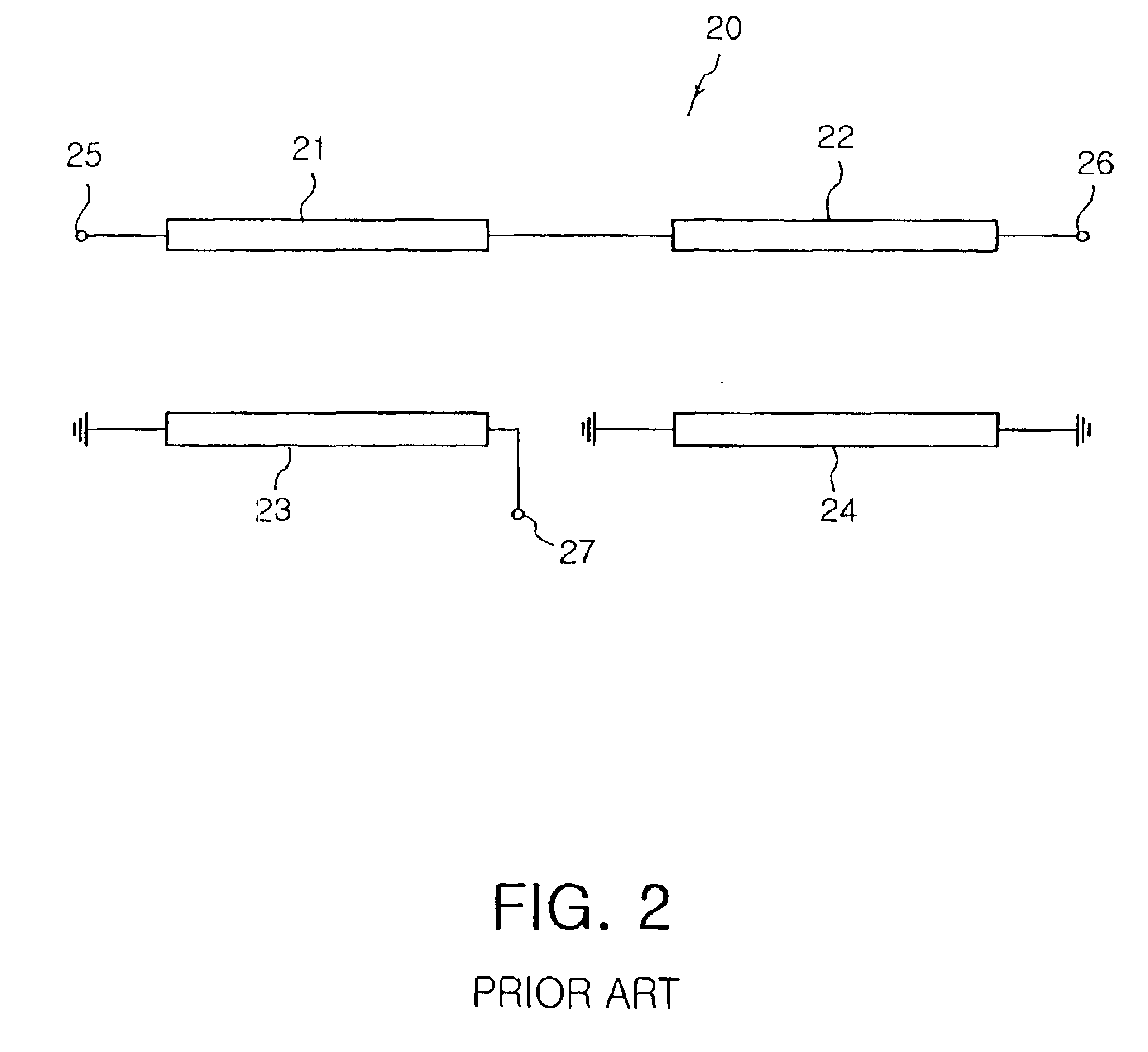
Further, the balun transformer of FIG. 2 is very hard to manufacture because the two couplers thereof are proposed to have a symmetrical structure.
The above-mentioned balun transformer 40 is simpler in structure than 4-line balun transformers, but is disadvantageous in that a branching point 44a must be formed in the unbalanced port 44, resulting in unnecessary reflection of high frequency signals.

Method used


Image

  • 3-line balun transformer
  • 3-line balun transformer
  • 3-line balun transformer

Examples


Embodiment Construction

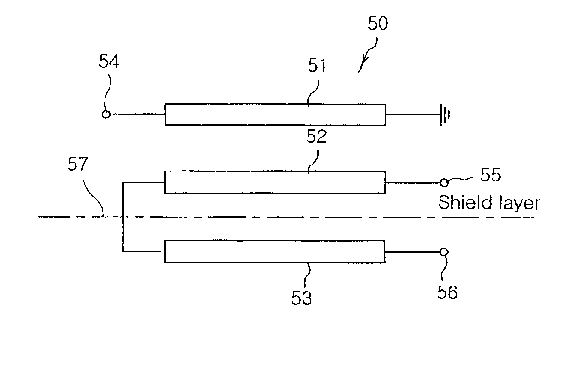
[0035]FIG. 5 is an equivalent circuit diagram of a 3-line balun transformer in accordance with the present invention, which is denoted by the reference numeral 50. As shown in this drawing, the balun transformer 50 comprises first to third lines 51˜53, each having first and second ends. The first to third lines 51˜53 are arranged in such a manner that they are mutually electromagnetically coupled. The first end of the first line 51 is connected to an unbalanced port 54 for input or output of an unbalanced signal and the second end thereof is connected to ground. The first ends of the second line 52 and third line 53 are connected to each other and the second ends thereof are connected respectively to first and second balanced ports 55 and 56 for output or input of signals which are the same in level and 180 degrees out of phase with each other, respectively.

[0036]The first to third lines 51˜53 are arranged in parallel to generate mutual electromagnetic couplings. That is, the first ...


PUM

PropertyMeasurementUnit
impedancesaaaaaaaaaa
distanceaaaaaaaaaa
lengthaaaaaaaaaa

Abstract

A 3-line balun transformer includes an unbalanced port for an unbalanced signal, first and second balanced ports for balanced signals, the balanced signals being the same in level and 180 degrees out of phase with each other, a first line having its first end connected to the unbalanced port and its second end connected to ground, a second line arranged in parallel with the first line while being spaced apart from the first line, the second line having its first end and its second end connected to the first balanced port, and a third line arranged in parallel with the second line while being spaced apart from the second, the third line having its first end connected to the first end of the second line and its second end connected to the second balanced port.

Description

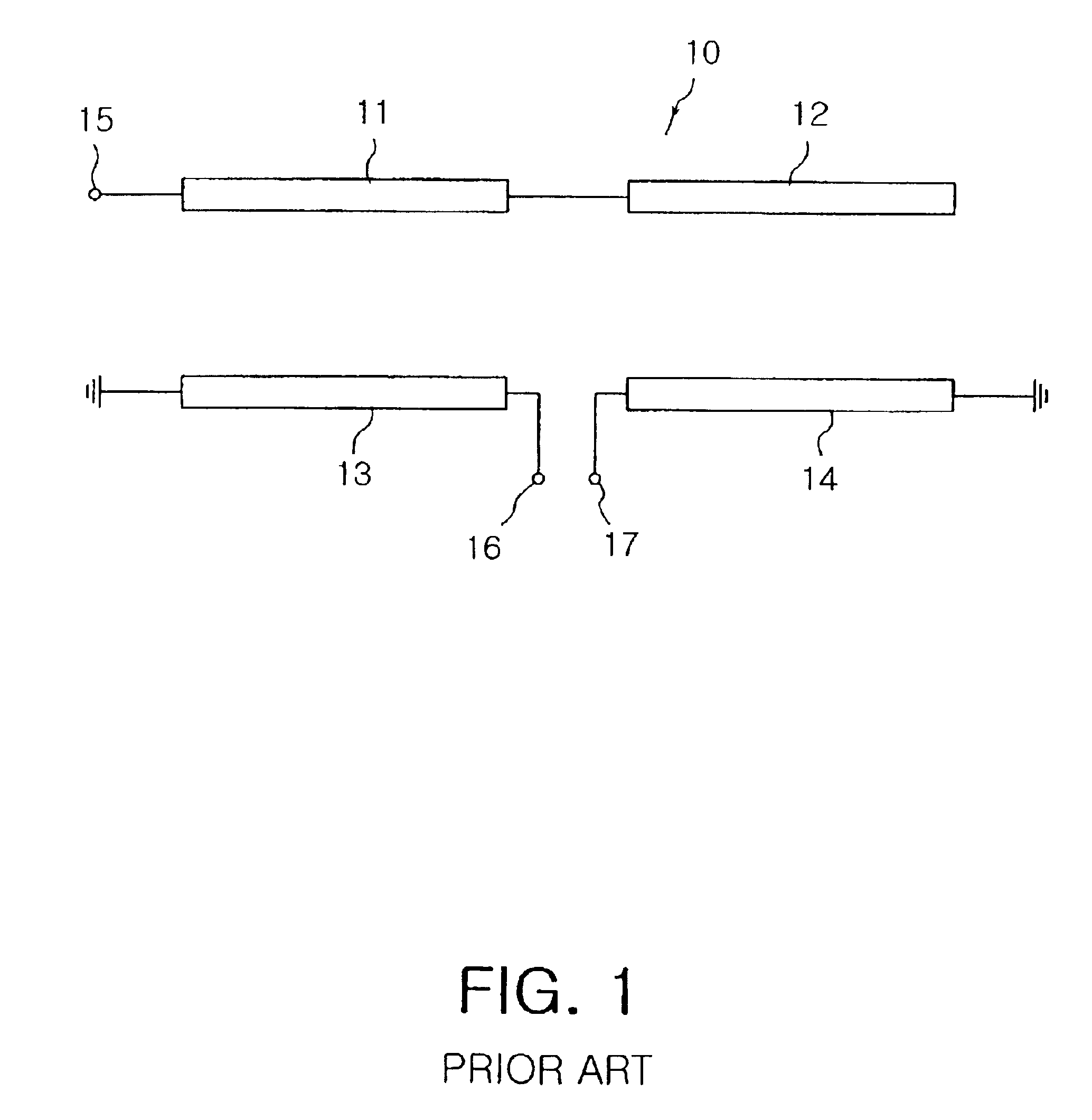
BACKGROUND OF THE INVENTION[0001]1. Field of the Invention[0002]The present invention relates to a balun transformer for converting balanced signals into an unbalanced signal or vice versa, and more particularly to a 3-line balun transformer which has a simple structure and is easy to design and manufacture.[0003]2. Description of the Related Art[0004]Generally, “balun” is an abbreviation for ‘balance to unbalance’, which typically signifies a circuit or structure for converting balanced signals into an unbalanced signal or vice versa.[0005]For example, a balun transformer may be required in a wireless communication field to connect a mixer, amplifier, etc. including balanced lines with components including unbalanced lines.[0006]A balun transformer may be implemented with a combination of transmission lines or a concentrated constant circuit, or in the form of a resonant waveguide in the case where it is employed in an antenna field.[0007]FIG. 1 is an equivalent circuit diagram of ...

Claims


Application Information

Patent Timeline
Patent Type & Authority Patents(United States)
IPC IPC(8): H01P5/10H01F19/06
CPCH01P5/10
Inventor PARK, DONG SEOKKIM, NAM CHULYOON, JEONG HOLEE, BYOUNG HWAPARK, SANG SOO
Owner SAMSUNG ELECTRO MECHANICS CO LTD
Learn More