
Bending apparatus for pipe and tubing

Inactive Publication Date: 2005-07-05
AMAESING TOOLS MFG
View PDF15 Cites 11 Cited by
  • Summary
  • Abstract
  • Description
  • Claims
  • Application Information

AI Technical Summary

Benefits of technology

[0008]It is yet another object of the invention to provide a manually operated bending apparatus that is self-aligning whereby precise horizontal and vertical bends can be accomplished without the user having to use additional effort in aligning the workpiece to achieve a desired bend.
[0009]It is yet another object of the invention to provide a bending apparatus that is of simple construction, yet is extremely reliable in allowing a user to efficiently configure workpieces for installation into a piping system.
[0010]It is yet another object of the invention to provide a combination of an existing vise and a bending apparatus to achieve bending of stock thereby eliminating more complex tools or machines that are normally used for bending stock.
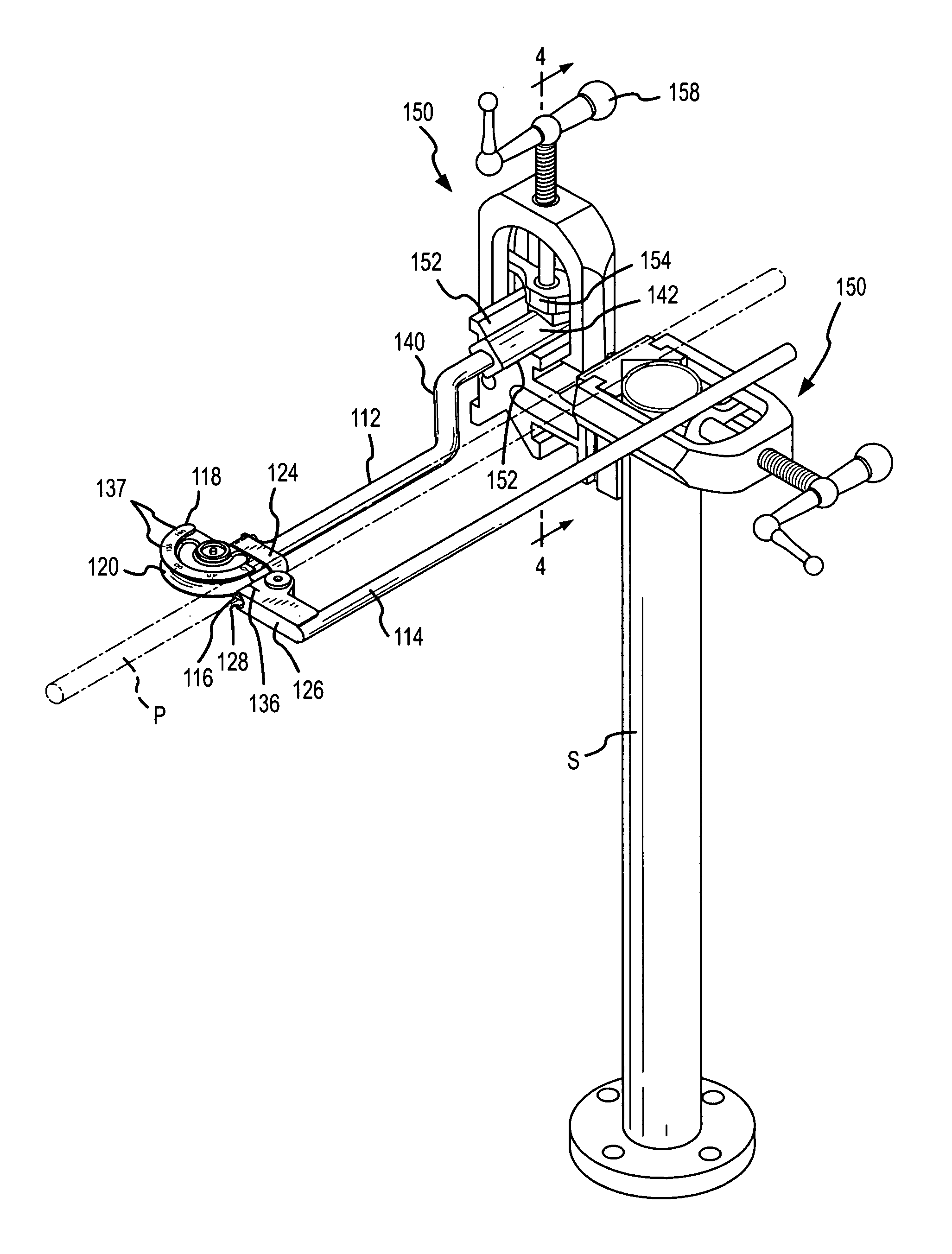
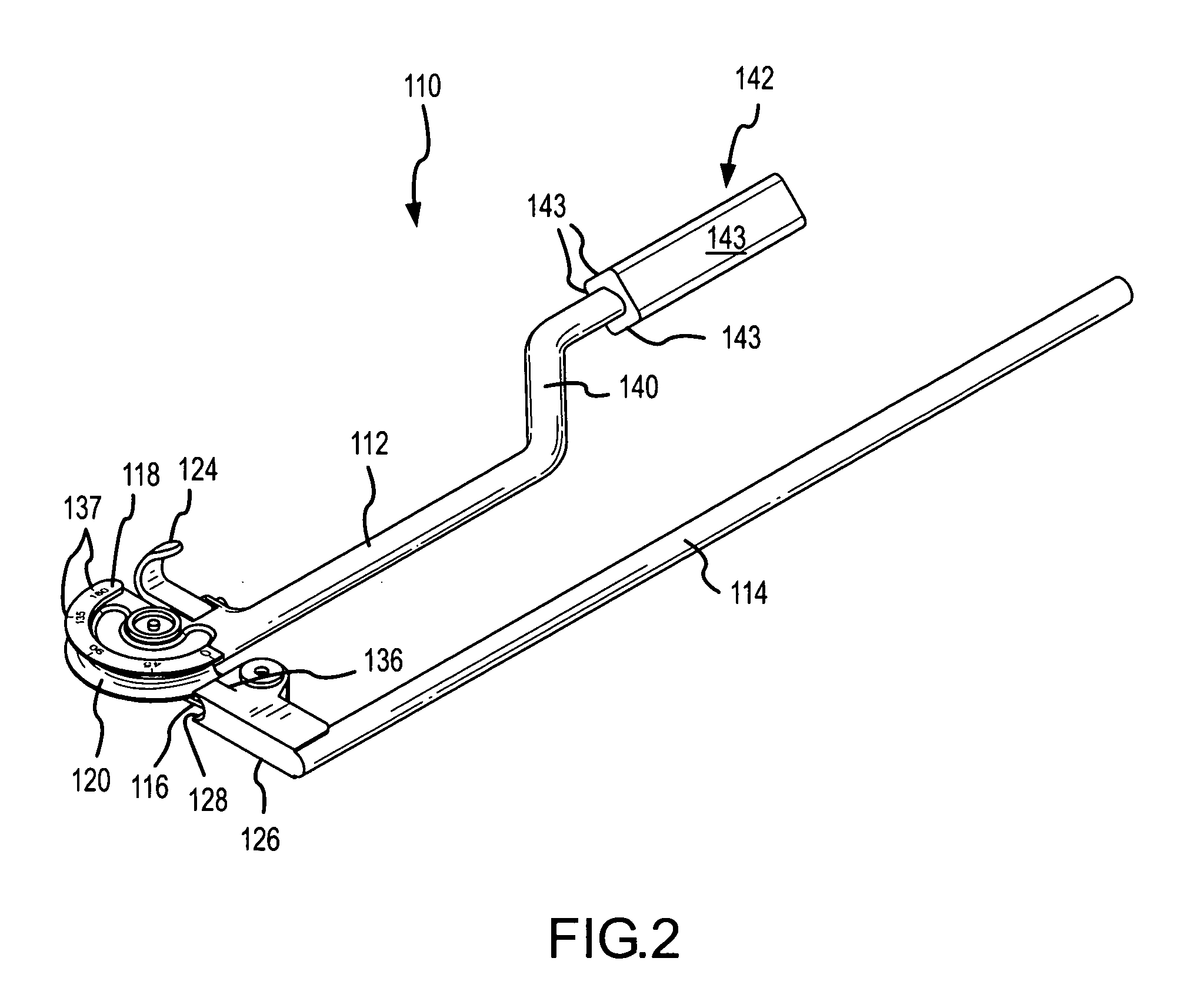
[0011]The present invention is directed to a hand operable bending apparatus that may be used for bending relatively thin walled stock directly at the job site. The apparatus is mounted to an existing vise used at the job site to secure stock to be installed into a pipe or tubing system. The bending apparatus includes a base member which carries a die for shaping the stock when a bending handle of the device is traversed through an arc thereby imparting a particular bend angle on the stock. The base includes an orienting block or member that is secured in the vise. The orienting member has a shape which complements the shape of the surfaces on the vise that contact the orienting member. A vise typically has a stationary jaw and a movable jaw which is movable to and away from the stationary jaw for securing the workpiece. Accordingly, the orienting member has a shape which complements the particular configuration of the vise so that the orienting member is rigidly held within the vise. The shape of the orienting member is also configured so that the bending apparatus is aligned to produce precise horizontal or vertical bends. Thus, a user of the tool can easily make a desired vertical or horizontal bend without having to realign the workpiece after it is secured in the bending apparatus, and otherwise does not have to exert additional effort in aligning the workpiece to achieve a desired bend.

Problems solved by technology

However, even with pipe bending devices similar to the one described in this reference, such devices still require substantial effort in assembly and disassembly.

Method used


Image

  • Bending apparatus for pipe and tubing
  • Bending apparatus for pipe and tubing
  • Bending apparatus for pipe and tubing

Examples


Embodiment Construction

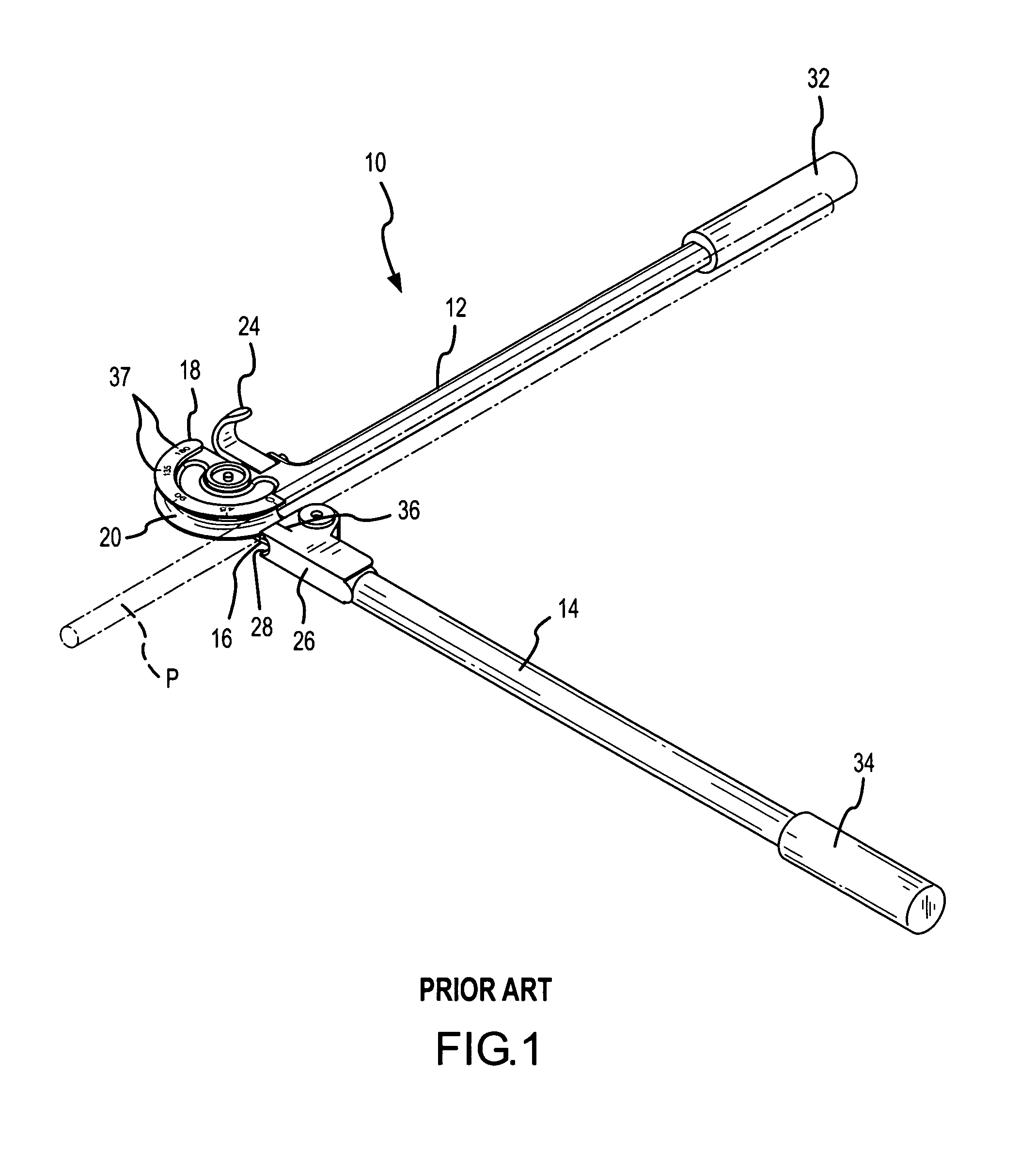
[0019]FIG. 1 illustrates a prior art hand operated bending apparatus 10. The apparatus 10 includes a first handle member or support 12, a second bending handle 14, and a connecting plate or member 16 that is at least pivotally mounted to the first handle member 12 thereby enabling the second handle member 14 to be rotated about the first handle member. Carried on the first handle or support 12 is an arcuate shaped die 18 having a channel 20 formed therein. The channel receives the workpiece to be bent. The channel may be sized to receive a particular diameter of stock, and it is also known to provide a plurality of stacked dies mounted to the support 12 thereby allowing the apparatus to manipulate different sized pieces of stock. Preferably, the connecting member 16 is also pivotally mounted to the second bending handle thereby allowing an operator to selectively position the engaging portion 26 of the handle 14 a desired distance from the channel 20, thereby also accommodating work...


PUM

PropertyMeasurementUnit
Angleaaaaaaaaaa
Angleaaaaaaaaaa
Angleaaaaaaaaaa

Abstract

A bending apparatus is especially adapted for mounting to a vise to hold the bending apparatus in an aligned position so that the bending apparatus may impart a desired angle bend on a workpiece. The bending apparatus includes an orienting member with a cross-sectional shape to complement the shape of the vice jaws. The bending apparatus when secured in the vise jaws is oriented horizontally or vertically, thus enabling the bending apparatus to precisely create horizontal and vertical bends in a workpiece. Bends may be created in succession without requiring a user to continually adjust the orientation of the workpiece or the bending apparatus itself.

Description

FIELD OF THE INVENTION[0001]This invention relates generally to devices for bending relatively thin metal stock such as pipe and tubing, and more particularly, to a manually operable bending apparatus that is self aligning when secured in a vice.BACKGROUND OF THE INVENTION[0002]There are a number of devices available and especially adapted for bending pipe, tubing, and other forms of metal stock. Some of these devices are hand tools that may be manually operated to impart a bend on the stock to thereby place the stock in a desired shape and configuration. There are also a number of devices that are designed for bending more substantial pieces of stock and therefore, are table mounted or mounted to a fairly large base. These latter type of devices may be power assisted or power operated.[0003]One example of a bending apparatus that is hand operated includes the apparatus disclosed in U.S. Pat. No. 4,167,865. This apparatus includes a base, a clamp on the base for holding portions of ...

Claims


Application Information

Patent Timeline
IPC IPC(8): B21D7/022B21D7/02
CPCB21D7/022B21D7/063
Inventor MAES, ROGER V.
Owner AMAESING TOOLS MFG
Learn More