
Network topology design apparatus and network topology design method, and recording medium recorded with a network topology design program

a topology design and network topology technology, applied in the field of network topology design apparatus and network topology design method, can solve the problems of difficult economic network construction and not always the best network cost performan

Inactive Publication Date: 2005-06-28
FUJITSU LTD
View PDF6 Cites 13 Cited by
  • Summary
  • Abstract
  • Description
  • Claims
  • Application Information

AI Technical Summary

Benefits of technology

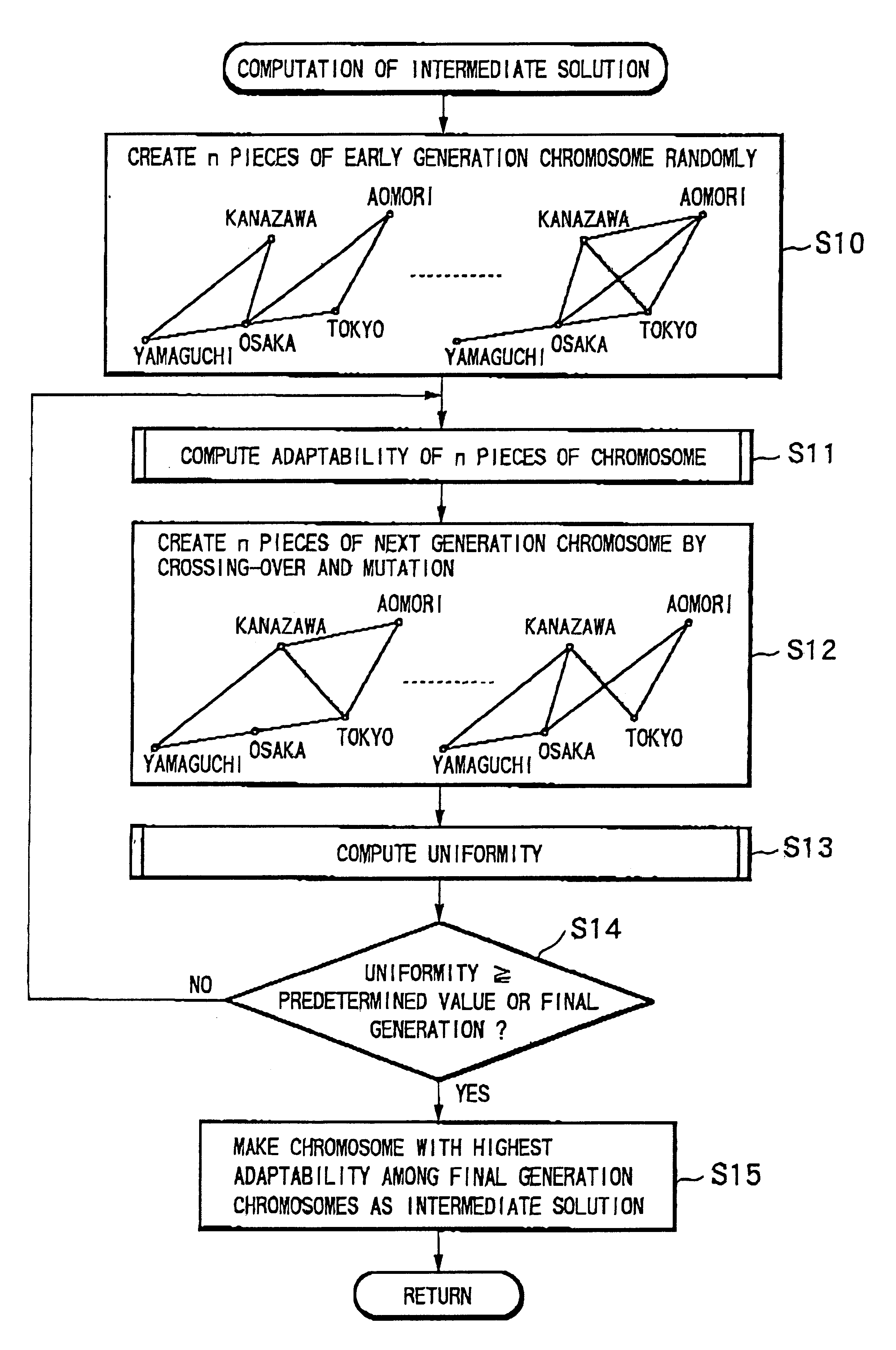
[0016]Furthermore, when designing a network topology, a two stage construction is used in which the communication path is considered (process stage (2)), and capacity of the communication line and fitness are computed (process stages (3) and (4)). Therefore, the solution space of the network topology can be drastically decreased. For example, in the case where a network topology connecting between n points by m kinds of communication lines is considered, the size of the solution space is “(m+1)n(n−1) / 2”. However, by having a two stage construction like the present invention, the size of the solution space becomes “2n(n−1) / 2”. Consequently, it is possible to design a network topology with excellent cost performance when using an electronic computer with a typical computing speed for the same period of time.
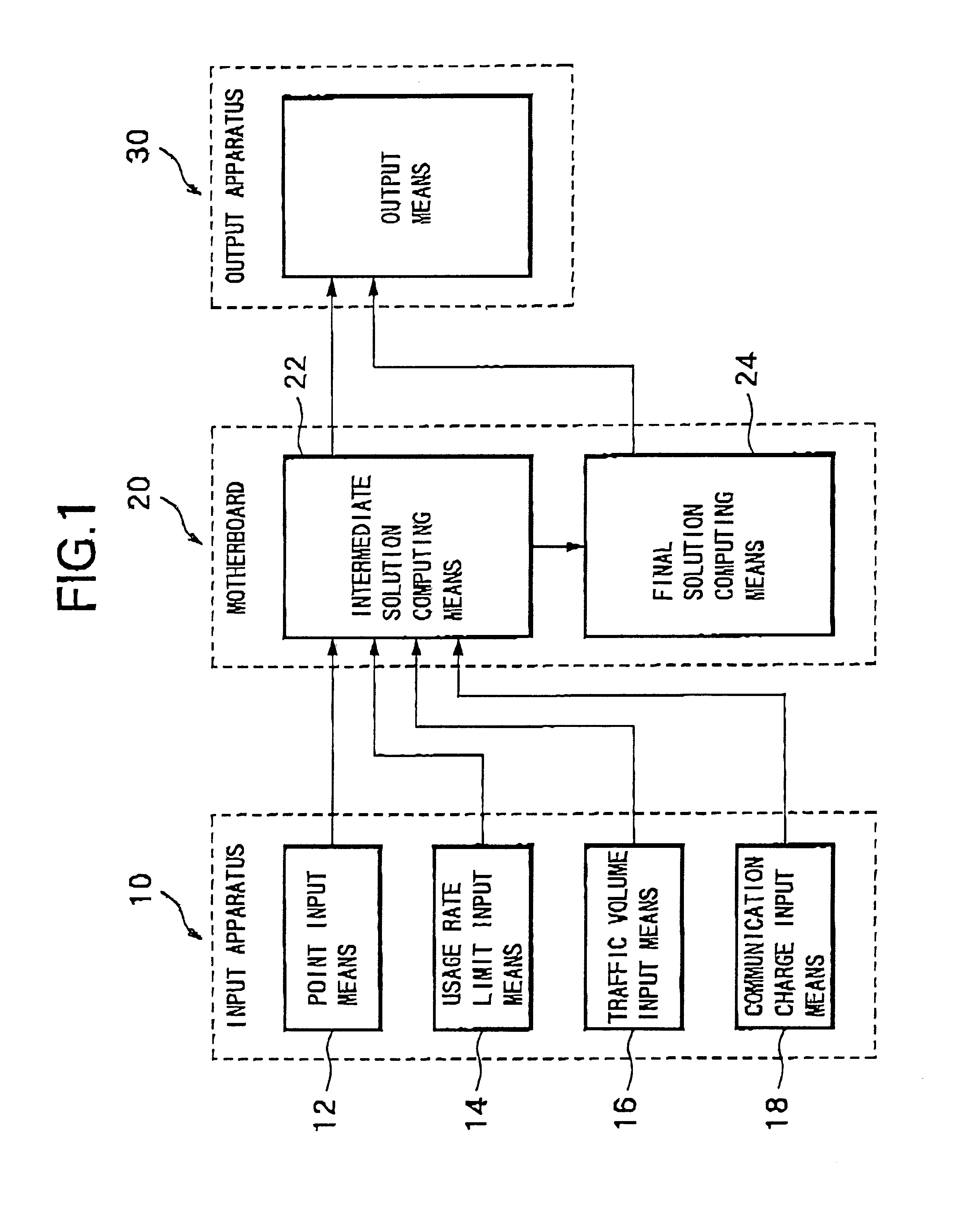
[0046]With such a construction, a network topology design program is recorded on a recording medium for realizing: a traffic volume input function, a cost information input function, and a line capacity determination function. Consequently, with a recording medium on which such a program is recorded, a network topology design apparatus according to the present invention can be easily constructed using a typical electronic computer system.

Problems solved by technology

Therefore, network cost performance is not always the best, and hence the situation is that economical network construction is difficult.

Method used


Image

  • Network topology design apparatus and network topology design method, and recording medium recorded with a network topology design program
  • Network topology design apparatus and network topology design method, and recording medium recorded with a network topology design program
  • Network topology design apparatus and network topology design method, and recording medium recorded with a network topology design program

Examples


Embodiment Construction

[0064]As follows is a detailed description of the present invention according to the appended drawings.

[0065]Firstly, the optimization problem of network topology (referred to hereunder as “optimization problem”) will be described. The optimization problem is to determine a network design such that communication cost is minimized, in other words the cost performance is the best, under a constraining condition that the communication line usage rate does not exceed a predetermined value in all communication lines connecting a plurality of points. Here, network design is to determine the points to be connected and the capacity of the communication lines connecting the points.

[0066]A network topology design apparatus (referred to hereunder as “design apparatus”) according to the present invention comprises an electronic computer which is provided with at least a central processing unit (CPU) and a memory, and processes the optimization problem according to a program stored in the memory...


PUM


Abstract

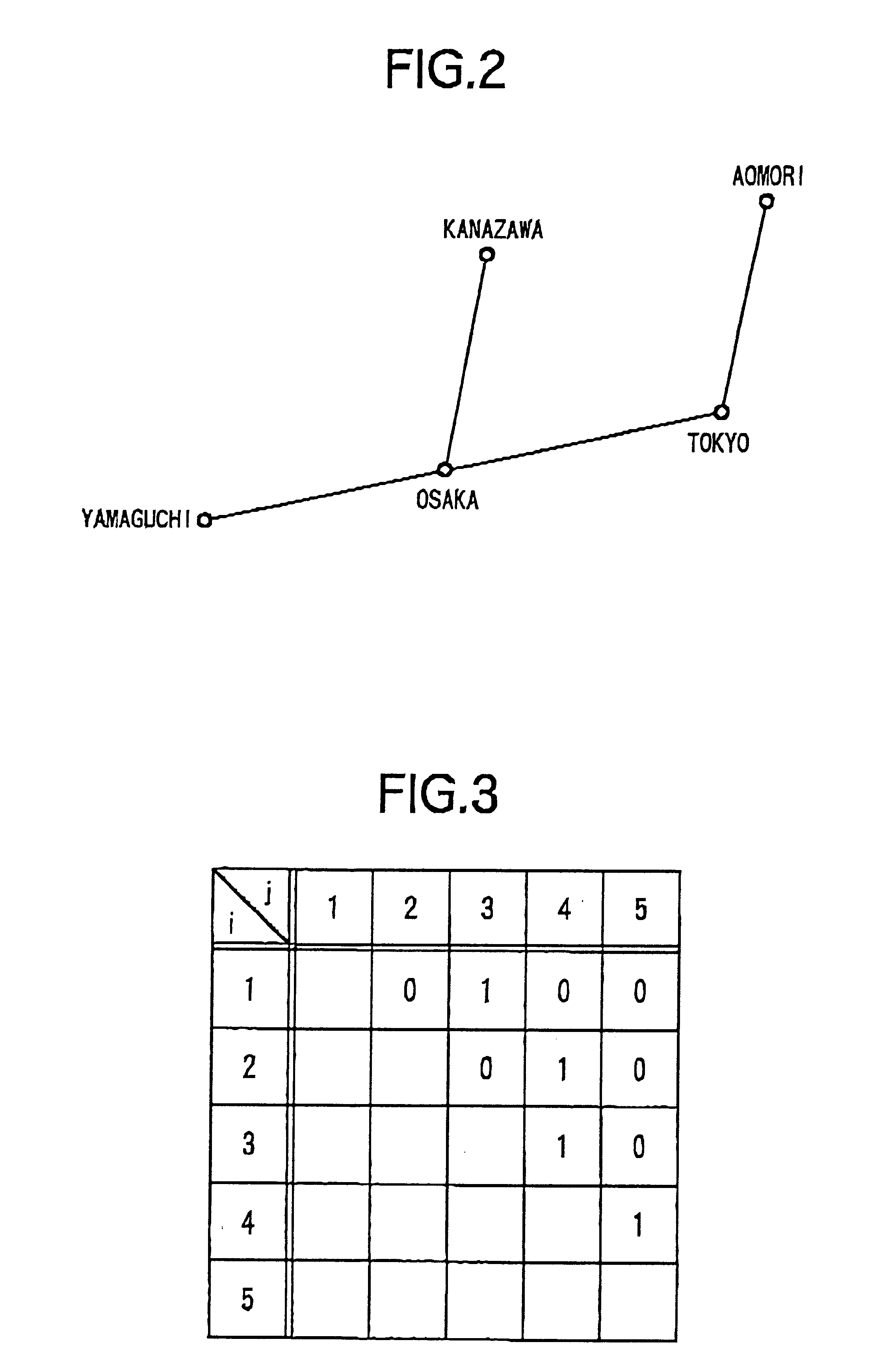
In a network topology design apparatus for designing a network topology connecting a plurality of points by communication lines so that a predetermined traffic volume is transmitted between the plurality of points, chromosomes wherein the network topology is represented in a matrix are created, and a genetic algorithm is applied to evolve the chromosomes in order to improve cost performance. Then by applying a local search method to the chromosomes which have been evolved by the genetic algorithm, to search the chromosomes in the neighborhood of the evolved chromosomes, a chromosome with a better cost performance is determined. In this way, genetic algorithms and local search methods are applied to design a network topology with excellent cost performance.

Description

[0001]This application is a continuation of PCT / JP99 / 01029 filed Mar. 3, 1999.TECHNICAL FIELD[0002]The present invention is related to a technique for designing a network topology, so that cost performance is optimized under predetermined conditions, when constructing a network connecting a plurality of points by communication lines.BACKGROUND ART[0003]With the large scale and complexity of recent networks, in enterprises and the like, the necessity to construct networks such as LAN (Local Area Network) / WAN (Wide Area Network) and the like as economically as possible has increased. Especially recently, as various connection services have been provided, it has become necessary to construct economical and effective networks according to a company's needs by combining these connection services appropriately.[0004]However, in many actual situations, network designers mainly analyze network traffic based on their personal experiences and simple calculations to determine network topology....

Claims


Application Information

Patent Timeline
Patent Type & Authority Patents(United States)
IPC IPC(8): G06N3/12G06N3/00H04L12/56G06F17/50H04L12/00
CPCH04L45/02G06N3/126
Inventor OHNISHI, MAKOTOFUNAKOSHI, WATARUOZAWA, MASANORI
Owner FUJITSU LTD
Learn More