
Radio base station equipment and mobile station equipment determining location of mobile station by associating with another radio base station or mobile station in a mobile communication system

a mobile communication system and radio base station technology, applied in direction finders using radio waves, instruments, wireless communication, etc., can solve the problems of insufficient determination accuracy, and inability to find that the determination target station is located in the wireless zone. achieve the effect of economically and accurately achieving the determination of the desired mobile station

Inactive Publication Date: 2005-06-21
FUJITSU LTD
View PDF8 Cites 118 Cited by
  • Summary
  • Abstract
  • Description
  • Claims
  • Application Information

AI Technical Summary

Benefits of technology

The present invention provides a radio base station equipment and mobile station equipment for achieving accurate and efficient determination of a desired mobile station or target station by applying a predetermined navigation to positional information about the determination station, even when the transmission characteristics of the radio channels vary or fluctuate. The invention also allows for flexible adaptation to changes in traffic, calls, and the state of operation of the determination stations, and can distribute the load on the radio base station equipment to prevent overload. The invention further provides a technique for achieving accurate and efficient determination of a desired target station, even when the number of mobile stations to be operated as determination stations cannot be secured. The invention also allows for stable and accurate performance of determination even when the local station is moved or the transmission characteristics of the radio transmission path fluctuate.

Problems solved by technology

Where the determination target station is located in a area where plural radio base stations are formed closely, it may be impossible to find that the determination target station is located in the wireless zone formed by the closest radio base station, due to overreach or multipath or for other cause.
Hence, there is the possibility that the accuracy of determination deteriorates uselessly.
Accordingly, the first prior art technique provides determination accuracy that is not always sufficiently high.
In addition, determination target stations located in areas where there are no radio base stations cannot become a subject of determination.
Consequently, stable determination is not accomplished.
Even when the determination is realized, the accuracy is not always sufficiently high.

Method used


Image

  • Radio base station equipment and mobile station equipment determining location of mobile station by associating with another radio base station or mobile station in a mobile communication system
  • Radio base station equipment and mobile station equipment determining location of mobile station by associating with another radio base station or mobile station in a mobile communication system
  • Radio base station equipment and mobile station equipment determining location of mobile station by associating with another radio base station or mobile station in a mobile communication system

Examples


first embodiment

[0217]FIG. 7 is a diagram illustrating the operation of the present invention.

[0218]The operation of the first embodiment of the present invention is described by referring to FIGS. 3-7 on the assumption that the various parts described above associate in the aforementioned manner.

[0219]In radio control station equipment 120, when an exchange sends “determination order” indicating the following items to a processor 125 (FIG. 7(1)), for example, the processor 125 sends the “determination order” as the aforementioned control information to a radio base station equipment 110-1 forming the wireless zone 110Z-1 (FIGS. 4(1) and 7(2)).

[0220]The mobile station equipments 90-1 to 90-3 are utilized as determination stations, and a determination target station (for simplicity, it is assumed that it is mobile station equipment 90-4) located in the wireless zone 110Z-1 in common with the mobile station equipments 90-1 to 90-3 should be radio determined.

[0221]In the radio base station equipment 1...

second embodiment

[0261]FIG. 9 is a diagram illustrating the operation of the present invention.

[0262]In this figure, processing items which correspond to their counterparts of FIG. 7 are indicated by the same reference numerals as used in FIG. 7 and will not be described in detail below.

[0263]The operation of the second embodiment of the present invention is hereinafter described by referring to FIGS. 3-6, 8 and 9.

[0264]The difference between the present embodiment and the first embodiment described above is that mobile station equipment (hereinafter referred to as the “agent mobile station”) corresponding to none of the mobile stations 90-1 to 90-3 (i.e., determination stations) and the mobile station equipment 90-4 (i.e., determination target station) acts for the radio base station equipment 110-1 and the processor 118 incorporated in the radio base station equipment 110-1 performs the following processing to permit this acting operation, as long as radio determination of the mobile stations 90-1...

third embodiment

[0277]The operation of the present invention is hereinafter described by referring to FIGS. 3 and 7.

[0278]The difference between the present embodiment and the first embodiment described above lies in the procedure of the following processing performed by the processors 93-1 to 93-3, 118-1 in the mobile station equipments 90-1 to 90-3 (i.e., determination stations) and the radio base station equipment 110-1.

[0279]As shown in FIG. 10, separate navigation selection tables 118A-1 to 118A-n indicative of navigation(s) (any one of 3r navigation, theta-theta navigation, 2r-theta navigation, and r-theta navigation) applicable according to the following combinations are allocated in certain areas of the main storage of the processors 118-1 to 118-n incorporated in the radio base station equipments 110-1 to 110-n, respectively.

[0280](1) Combinations of determination stations that are transmitting ends of “determination response” including some valid arrival angles and relative distances

[0281...


PUM


Abstract

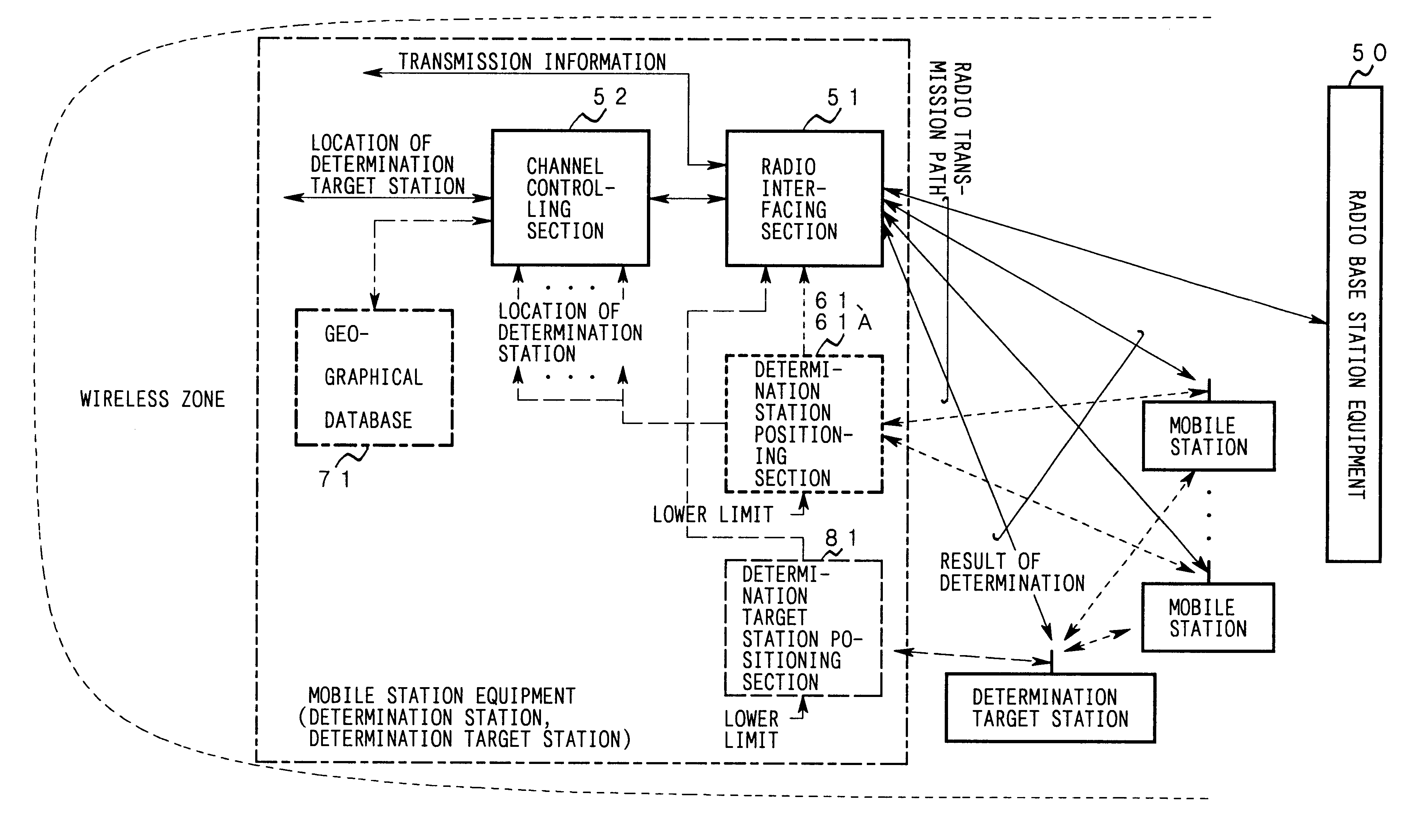
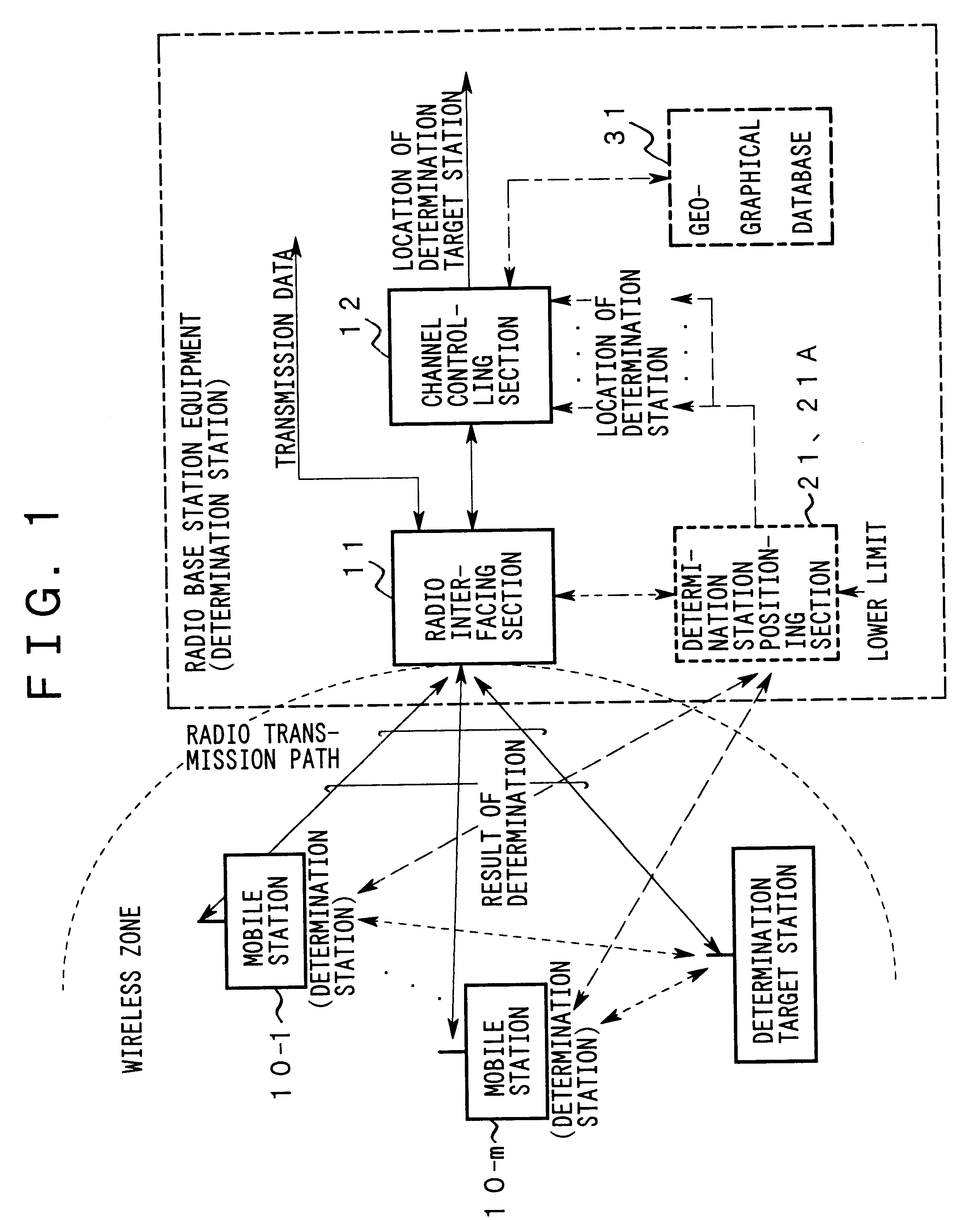
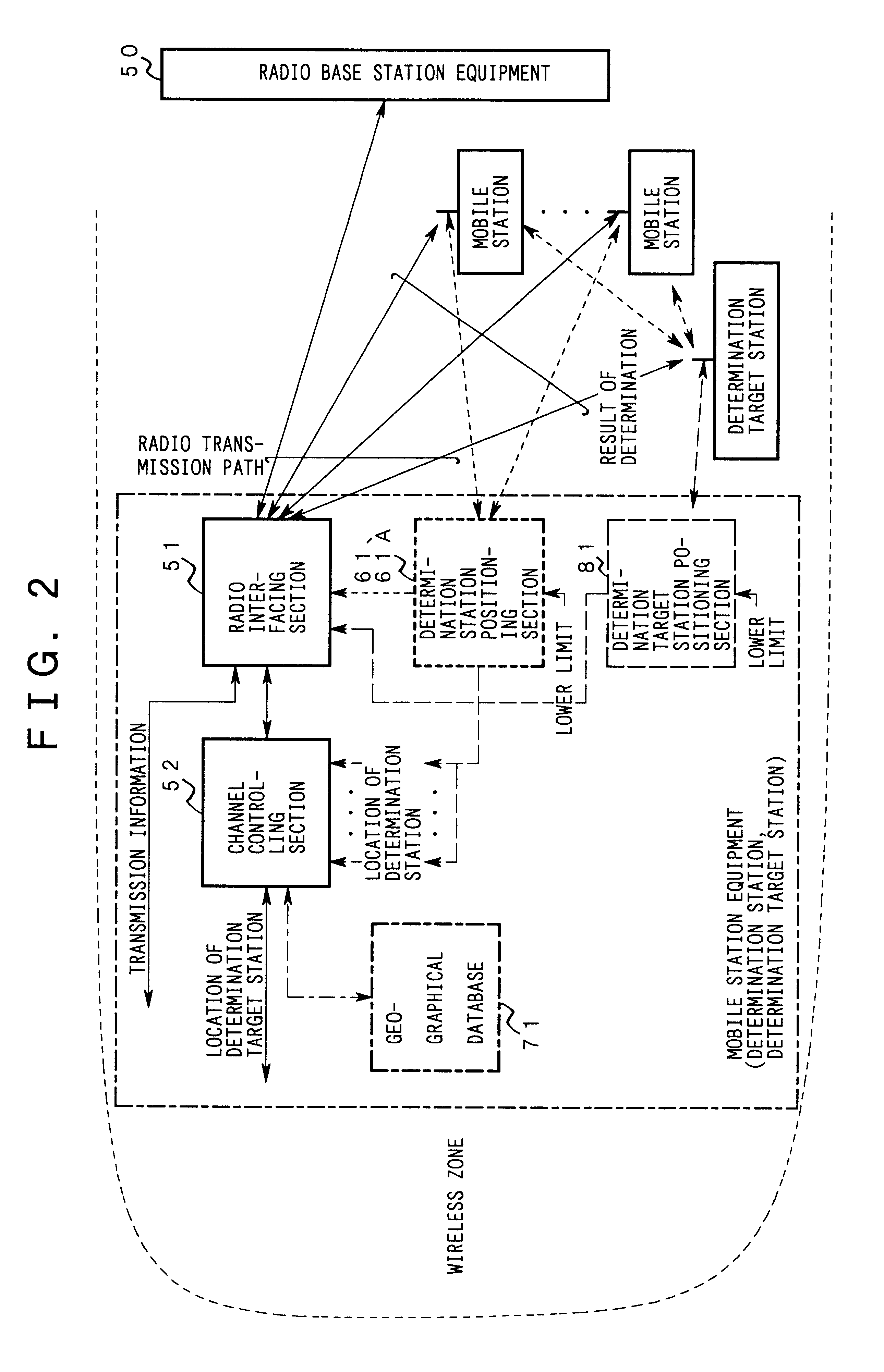
This invention relates to a radio base station equipment and a mobile station equipment in a mobile communication system that operate as determination stations adapted for a predetermined navigation or associate with other radio base station(s) or mobile station(s) to radio-determine the location of a desired mobile station. The mobile communication system achieves a radio determination economically and reliably while flexibly adapting itself to the substantial traffic distribution and transmission characteristics in individual wireless zones as well as the zone configuration, channel allocation, the procedure of channel control, and the structure of hardware.

Description

BACKGROUND OF THE INVENTION[0001]1. Field of the Invention[0002]The present invention relates to radio base station equipment and mobile station equipment for determining the locations of mobile stations in a mobile communication system.[0003]2. Description of the Related Art[0004]In recent years, because of liberalization of the market and competition among communication service providers, telephone charges and the prices of terminal equipments have been lowered. Furthermore, portable terminal equipments having various functions adapted for users' needs have been put into practical use. Consequently, the use of mobile communication systems has become rapidly widespread.[0005]According to the aforementioned competition and the development of techniques adapted for multimedia communications, mobile communication systems are required to have higher added values. For example, it is strongly required that determination services be offered to a terminal equipment possessed by a person wh...

Claims


Application Information

Patent Timeline
Patent Type & Authority Patents(United States)
IPC IPC(8): G01S5/02H04Q7/20H04Q7/34H04W60/00H04W64/00
CPCH04W64/00
Inventor SAWADA, KENSUKEKAWAGUCHI, NORIYUKINAKAMURA, SATOSHIKUBO, TOKUROKIMURA, DAIMINOWA, MORIHIKONAGATANI, KAZUO
Owner FUJITSU LTD
Learn More