
Mast device for a submarine

a technology for mast devices and submarines, applied in the direction of antennas, buoys, communication devices, etc., can solve the problems of corresponding manufacturing costs and a larger space requiremen

Inactive Publication Date: 2005-06-21
MASCHENBAU GABLER
View PDF12 Cites 19 Cited by
  • Summary
  • Abstract
  • Description
  • Claims
  • Application Information

AI Technical Summary

Benefits of technology

[0004]The object of the invention lies in further developing a mast device of the initially mentioned type such that in comparison to its extended condition, it permits a greater observation diving depth of the submarine for the information exchange above the water.
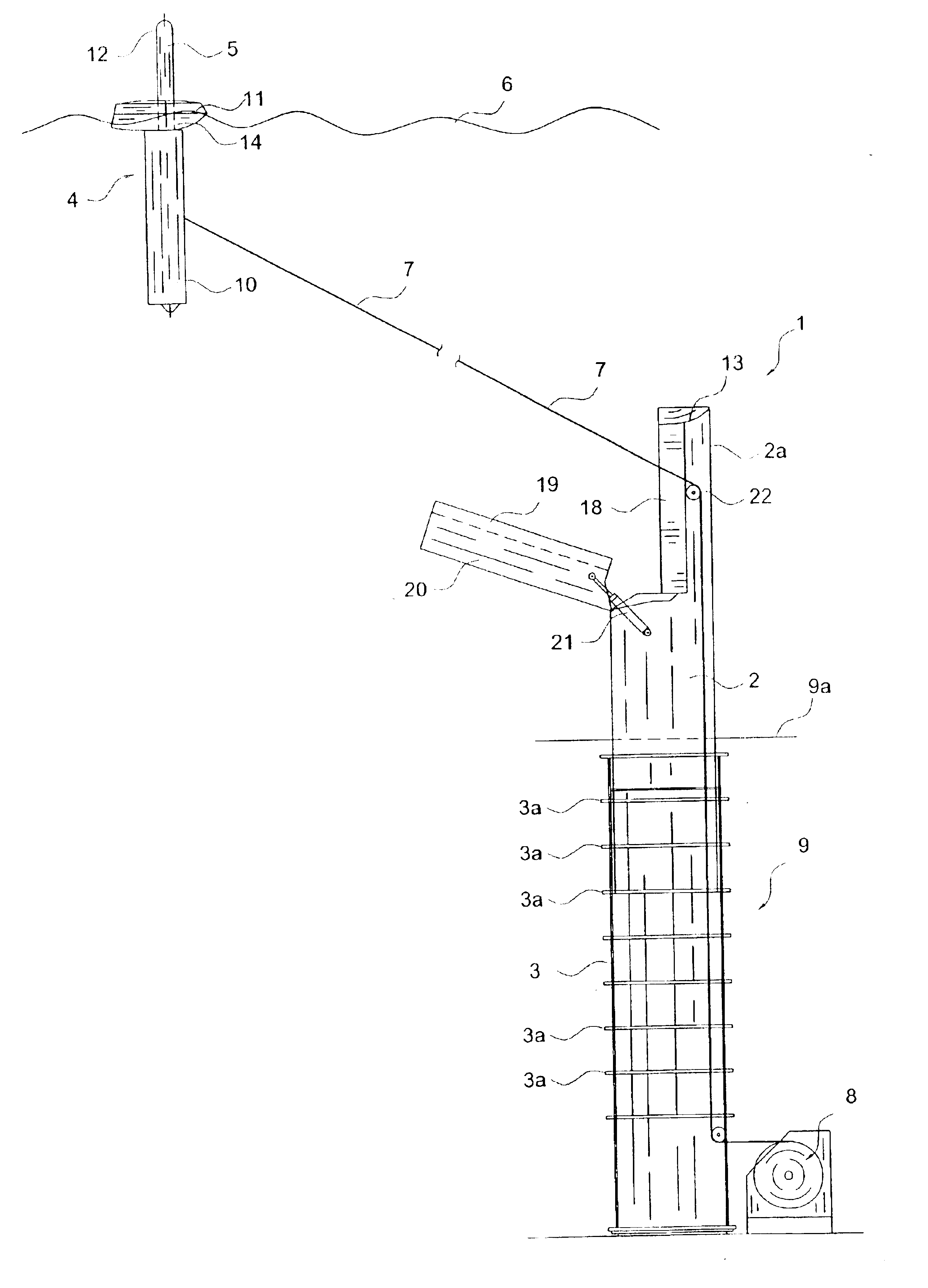
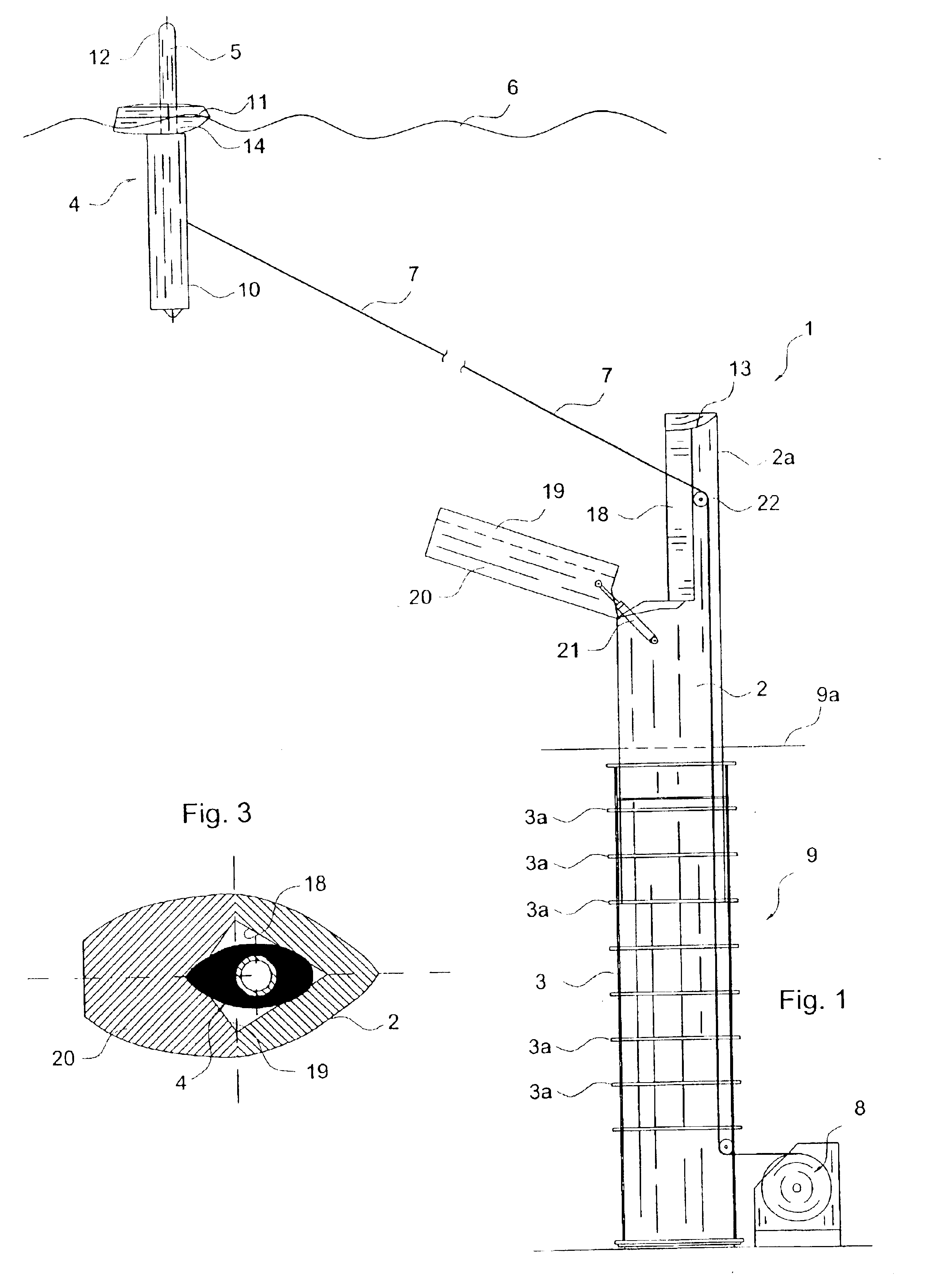
[0008]By way of the inventive design of the mast device it is possible for the submarine to be able to assume such a i.e. deeper observation diving depth which is greater than that of the merely extended mast device. A further advantage lies in the fact that a separate buoyant information unit additional to the mast device is done away with, from which there leads the further advantage that no special space or place on or in the submarine need be provided for a floatable information unit and thus also the manufacturing costs for a separate information unit and the design of a space for its positioning in the retracted condition are done away with. A further advantage of the inventive mast device lies in the fact that its information unit may also be used in a conventional manner for emitting and / or receiving information above the water surface, i.e., that the mast is extended but that the buoyant unit with the information means remains on the upper end of the mast.
[0010]A further advantageous feature of the mast device lies in the fact that the mast upper end comprises a removable mast wall part for simplifying the release and repositioning of the buoyant unit from or on the mast upper end. Preferably the mast wall part is designed laterally pivotable, e.g. with the help of a piston-cylinder unit.

Problems solved by technology

With these known buoy designs it is however disadvantageous that the main body of the submarine must additionally be specifically designed for the installation or accommodation of the buoyant buoy, which entails corresponding manufacturing costs and a larger space requirement.

Method used


Image

  • Mast device for a submarine
  • Mast device for a submarine
  • Mast device for a submarine

Examples


Embodiment Construction

[0023]According to FIG. 1 the mast device indicated generally at 1 comprises a mast 2 which is vertically traversable in the conventional manner, a guide means 3 for the mast, a buoyant unit 4 with conventional information means 5 for emitting and / or receiving information of all types above the surface of the water, a flexible coupling means 7, preferably in the form of a wire cable or a carbon fibre cable, with which there may be combined signal leads for electrical signals to and from the information means 5, as well as a winch 8 for letting out and again drawing in the coupling means, in order to let the buoyant unit 4 rise to the surface of the water 6 or to retract it again from this. The winch 8 may be provided outside the guiding means 3, e.g. below next to it, or in the mast (FIG. 9). The mast 2 has according to FIG. 3 a hydrodynamic cross sectional profile and is vertically traversable in a conventional manner by way of a piston-cylinder unit (not shown), so that it may be ...


PUM


Abstract

The mast device for a submarine comprises a guiding means, a vertically traversable mast guided therein and information means which are provided at the mast upper end and which are in electrical interaction with the inside of the submarine for emitting and receiving information. The information means are arranged in a buoyant unit held on the mast upper end without connection to this. The buoyant unit is fastened to a flexible coupling means which may be let out and retracted and which is of the length essentially of the maximum desired observation depth of the submarine.

Description

BACKGROUND OF THE INVENTION[0001]The invention concerns a mast device for a submarine.[0002]Such a known mast device for submarines is provided such that at the upper end of the mast which is vertically traversable in a guiding means there is provided an information means which is in interactive connection with the control station in the inside of the submarine for receiving and emitting information. The information means is rigidly connected to the upper end of the mast and itself may be extended out by a certain amount so that it projects from the mast. If information is to be emitted and received, the submarine travels to the observation depth which corresponds to the height of the extended mast so that the information means is located above the water surface.[0003]Furthermore it is known, e.g. by way of the DE patent document 758 461 and by way of DE 28 37 134 A1 to provide a buoyant unit in the form of a buoy which comprises an optical observation means. The buoy is releasably ...

Claims


Application Information

Patent Timeline
IPC IPC(8): B63G8/00B63G8/38H01Q1/12H01Q1/27H01Q1/34B63B22/18B63B22/00
CPCH01Q1/34H01Q1/12B63G8/38B63B22/18B63B2203/00
Inventor KRUGER, LORENZSPAHR, JURGENWANTIG, ULRICHSCHARF, WOLFGANG
Owner MASCHENBAU GABLER
Learn More