Device for position indication and detection of guidance errors

Inactive Publication Date: 2005-06-14
DR JOHANNES HEIDENHAIN GMBH
View PDF32 Cites 14 Cited by
  • Summary
  • Abstract
  • Description
  • Claims
  • Application Information

AI Technical Summary

Benefits of technology

[0008]It is an object and advantage of the present invention to disclose a device for position indication and the detection of guidance errors which, starting from a customary, high-resolution position measuring device, requires as few modifications as possible in order to also perform a highly precise detection of guidance errors along at least one predetermined axis.
[0009]The above object and 
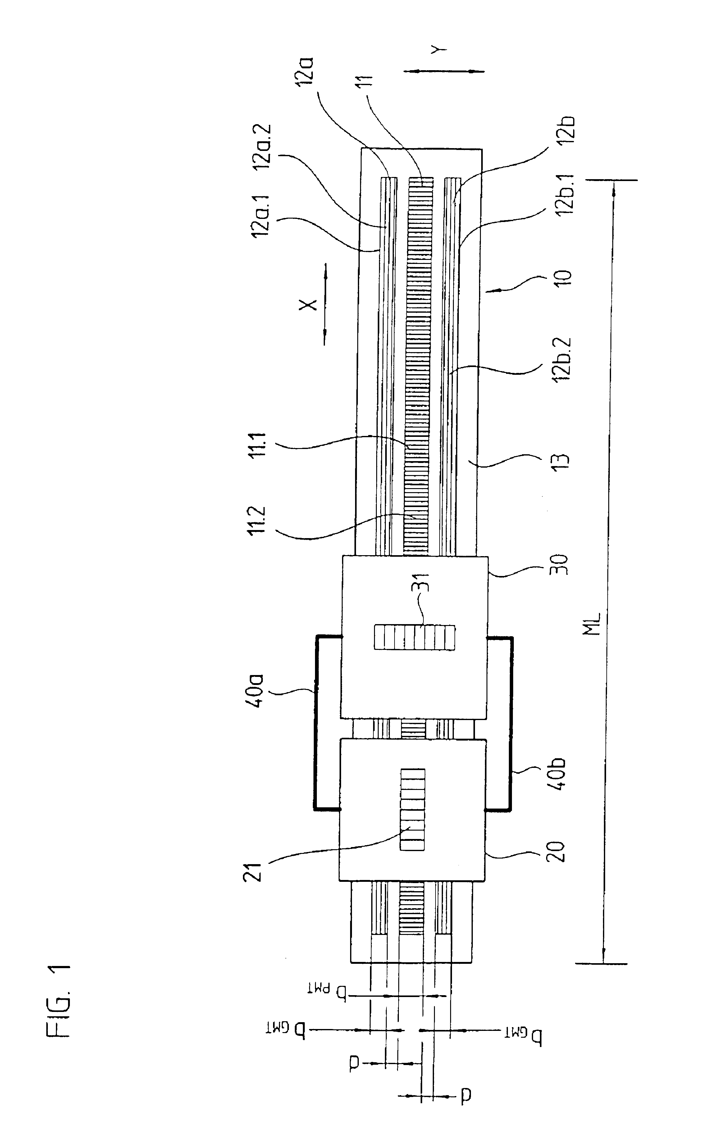
advantage are attained by a device for position indication and the detection of guidance errors that includes a scale that has a position measuring graduation arranged in a position measurement direction. A first guidance error measuring graduation which is arranged perpendicularly with respect to the position measurement graduation and a second guidance error measuring graduation which is arranged perpendicularly with respect to the position measurement graduation, wherein the first guidance error measuring graduation and the second guidance error measuring graduation are arranged on both sides of and adjacent to the position measuring graduation. A position indication scanning unit movable with respect to the scale, wherein the position indication scanning unit scans the position measuring graduation for generating position measurement signals. A guidance error scanning unit that is movable with respect to the scale, wherein the guidance error scanning unit scans the first guidance error measuring graduation for generating guidance error measurement signals.
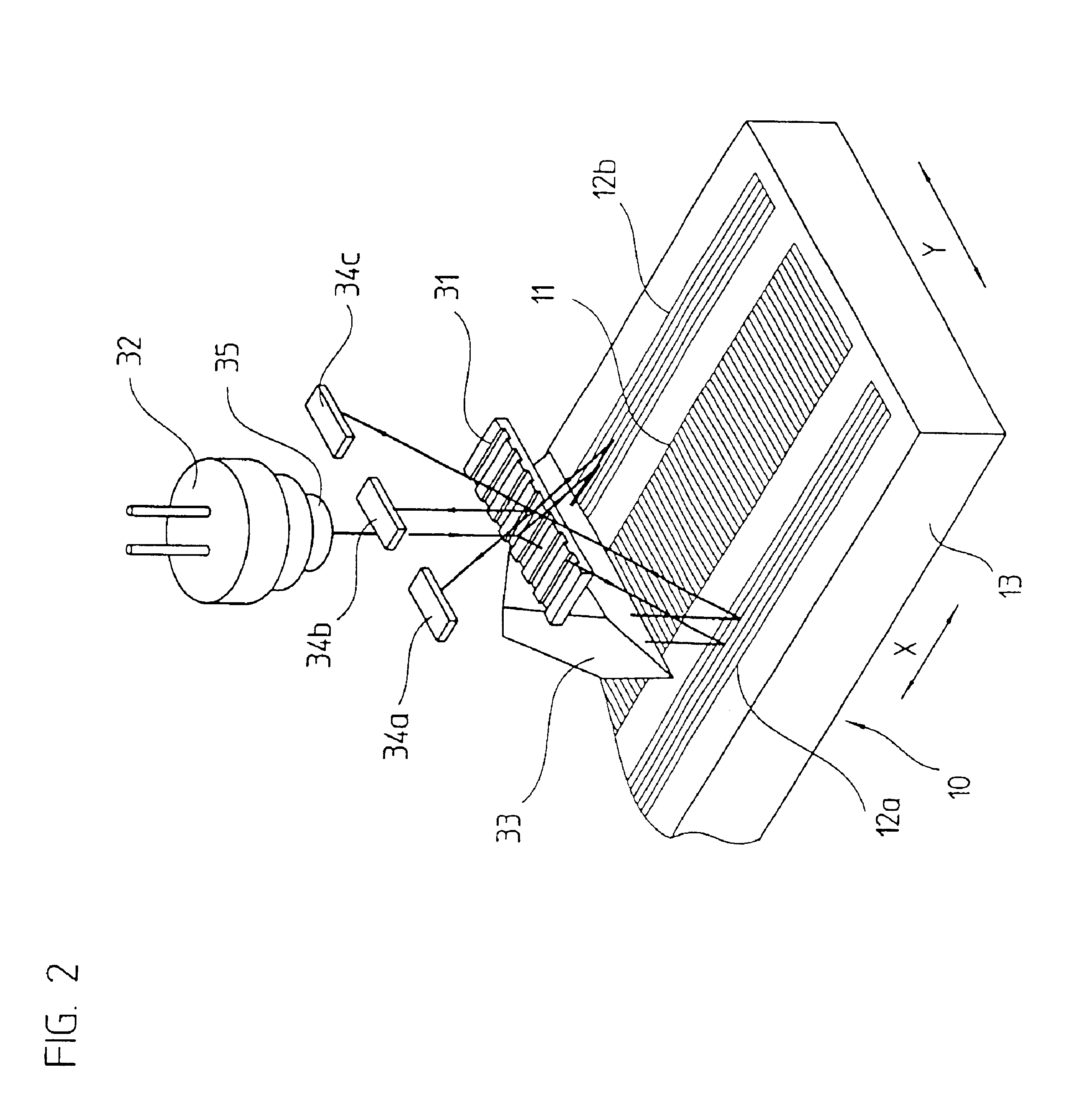
[0010]In accordance with the present invention, a high-resolution position measuring device, such as is known from EP 0 387 520 B1 and corresponding U.S. Pat. No. 5,079,418, the entire contents of which is incorporated herein by reference, for example, is modified in such a way that a simultaneous detection of guidance errors is possible with it. At least two guidance error measuring graduations, each of which is oriented vertically with respect to the position measuring graduation, are arranged at the sides of the scale of the device of the present invention and adjoining a conventional position measuring graduation in the form of an incremental graduation. Preferably, two identically designed scanning units, which merely need to be arranged turned by 90° with respect to each other, are provided for scanning the different measurement graduations. One of the two scanning units is used as the position indication scanning unit, which in a known manner scans the position measuring graduation in the measurement direction to generate position measurement signals. The second scanning unit, functioning as a graduation error scanning unit, scans the guidance error measuring graduations for generating guidance error measurement signals. Together with the position indication scanning unit, the guidance error scanning unit is movable with respect to the scale along the measurement direction.
[0011]Thus, compared with the known position measuring device from EP 0 387 520 B1, only the additional arrangement of the two guidance error measuring graduations on the scale, as well as a second, identical, scanning unit are required, in order to perform the position indication, as well as the detection of guidance errors, with a single device.
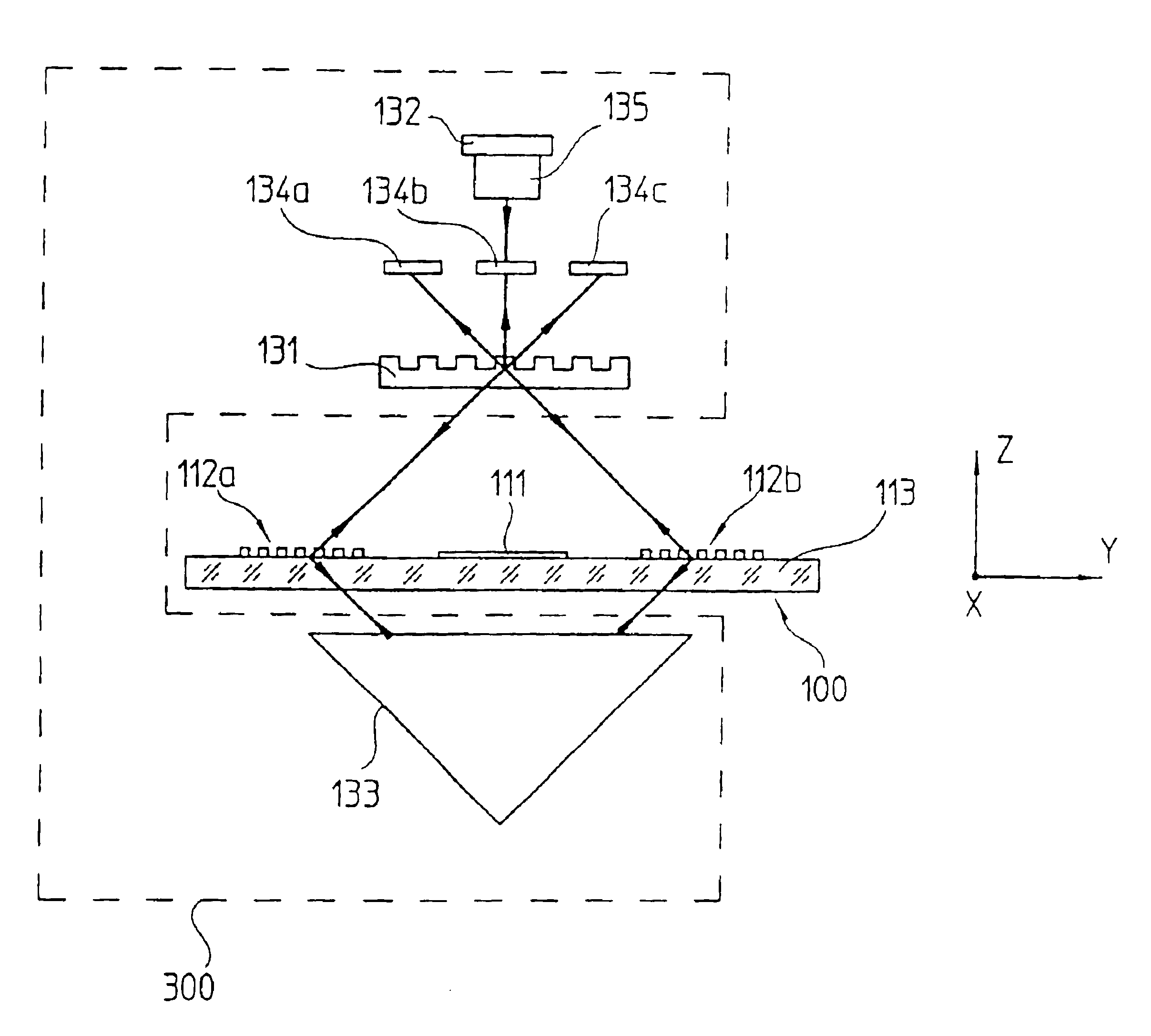
[0012]The generation of the position measurement signals, as well as the generation of the guidance error measurement signals, is based on an interferential scanning system, i.e. a correspondingly high resolution or precision is assured for each of the two measurements.
[0013]Moreover, the arrangement of the position measuring graduation and the two guidance error measuring graduations on the scale is extremely space-saving, i.e. no large structural volumes are required on the part of the scale.

Problems solved by technology

However, here the absolute position indication is performed with a relatively rough resolution, therefore this device is not suitable for high-precision applications.

Method used


Image

  • Device for position indication and detection of guidance errors
  • Device for position indication and detection of guidance errors
  • Device for position indication and detection of guidance errors

Examples


Embodiment Construction

[0019]A first exemplary embodiment of the device in accordance with the present invention is schematically represented in a top plan view in FIG. 1. For reasons of clarity, not all elements, in particular on the part of the respective scanning units 20, 30, have been represented.

[0020]As can be seen in FIG. 1, the device in accordance with the present invention for position indication and detection of guidance errors includes a scale 10, as well as two scanning units 20, 30, which can be moved with respect to the scale 10 in a measurement direction x. In actual use, the scale 10 is here movably arranged with respect to the two scanning units 20, 30, however, only the possible relative movement between the scale 10 and the scanning units 20, 30 is essential. In what follows, the two scanning units 20, 30 will be called position indication scanning unit 20 and guidance error scanning unit 30, respectively. Both scanning units 20, 30 are movable together with respect to the scale 10, o...


PUM


Abstract

A device for position indication and the detection of guidance errors that includes a scale that has a position measuring graduation arranged in a position measurement direction. A first guidance error measuring graduation which is arranged perpendicularly with respect to the position measurement graduation and a second guidance error measuring graduation which is arranged perpendicularly with respect to the position measurement graduation, wherein the first guidance error measuring graduation and the second guidance error measuring graduation are arranged on both sides of and adjacent to the position measuring graduation. A position indication scanning unit movable with respect to the scale, wherein the position indication scanning unit scans the position measuring graduation for generating position measurement signals. A guidance error scanning unit that is movable with respect to the scale, wherein the guidance error scanning unit scans the first guidance error measuring graduation for generating guidance error measurement signals.

Description

[0001]Applicant claims, under 35 U.S.C. § 119, the benefit of priority of the filing date of Sep. 16, 1999 of a German patent application, copy attached, Serial Number 199 44 395.5, filed on the aforementioned date, the entire contents of which is incorporated herein by reference.BACKGROUND OF THE INVENTION[0002]1. Field of the Invention[0003]The present invention relates to a device for position indication and the detection of guidance errors, including a scale and a position indication scanning unit as well as a guidance error scanning unit.[0004]2. Discussion of Related Art[0005]Occasionally there is a requirement in connection with modern precision machine tools or coordinate-measuring apparatus to detect, besides the exact indication of the position along a machine axis, possibly existing guidance errors of the respective axis. The detection by measurement techniques of one of the different guidance errors is also called straightness measuring. It is possible to computationally...

Claims


Application Information

Patent Timeline
IPC IPC(8): G01B5/00G01B11/30G01B11/00G01D5/347G01D5/38G02B5/18
CPCG01B11/306G01B5/0009
Inventor SPANNER, ERWIN
Owner DR JOHANNES HEIDENHAIN GMBH
Why Eureka
Try Eureka