
Agent reactive scheduling in an automated manufacturing environment

a manufacturing environment and agent technology, applied in the direction of total factory control, programme control, electric programme control, etc., can solve the problems of lack of advance scheduling, difficult and complicated routing, scheduling, and tracking material through the fab,

Inactive Publication Date: 2005-06-14
OCEAN SEMICON LLC
View PDF22 Cites 22 Cited by
  • Summary
  • Abstract
  • Description
  • Claims
  • Application Information

AI Technical Summary

Problems solved by technology

Controlling a semiconductor factory fabricating such integrated circuits, however, is a challenging task.
Routing, scheduling, and tracking material through the fab is a difficult and complicated task, even with the assistance of a computerized factory control system.
Although MES systems are sufficient for tracking lots and machines, such systems suffer several deficiencies, the most obvious of which are their passive nature, lack of advance scheduling and inability to support highly automated factory operations.
If the WFT does not retrieve the lot soon enough, or neglects to initiate processing at the earliest available time, the machine becomes idle and production is adversely impacted.
However, the presence of WFTs also inevitably introduces some inefficiencies.
There typically is a large difference between the performance of the best WFT and the performance of the worst WFT.
A WFT typically simultaneously monitors the processing of multiple tools and lots, making it difficult to focus on an individual lot or tool.
Furthermore, the size and complexity of the modern fabrication process flows makes it exceedingly difficult for a WFT to foresee and prevent downstream bottlenecks or shortages arising from upstream activities.
Shift changes, rest breaks, and days off for the WFT also create inefficiencies or machine idle time that adversely impact the manufacturing process flow.
Thus, factory control systems utilized in today's wafer fabs are passive and do not enable a high degree of automation.
As a fab's production ramps and more complex processes are introduced, it becomes more difficult to meet the increased complexity and volume without increasing staff or system capabilities.
WFTs visibility of upstream and downstream operations, tool state, work-in-process and resource availability is limited.
However, key logistical decisions are frequently based on this limited and dated information, which is only partially provided by factory control systems.
Shift changes disrupt the operation of the fab as the technicians are temporarily unable to provide required monitoring and coordination.
Despite the best efforts of the technicians, utilization of tools suffer, adversely impacting other key factory metrics including cycle time, inventory levels, factory output and mix.
With the need for intrabay material handling to transport 12-inch wafers in new 300 mm wafer fabs, significant additional complexity is introduced.
Conventional factory control systems are not capable of providing this level of detailed scheduling and execution control.

Method used


Image

  • Agent reactive scheduling in an automated manufacturing environment
  • Agent reactive scheduling in an automated manufacturing environment
  • Agent reactive scheduling in an automated manufacturing environment

Examples


Embodiment Construction

[0030]Illustrative embodiments of the invention are described below. In the interest of clarity, not all features of an actual implementation are described in this specification. It will of course be appreciated that in the development of any such actual embodiment, numerous implementation-specific decisions must be made to achieve the developers' specific goals, such as compliance with system-related and business-related constraints, which will vary from one implementation to another. Moreover, it will be appreciated that such a development effort, even if complex and time-consuming, would be a routine undertaking for those of ordinary skill in the art having the benefit of this disclosure.

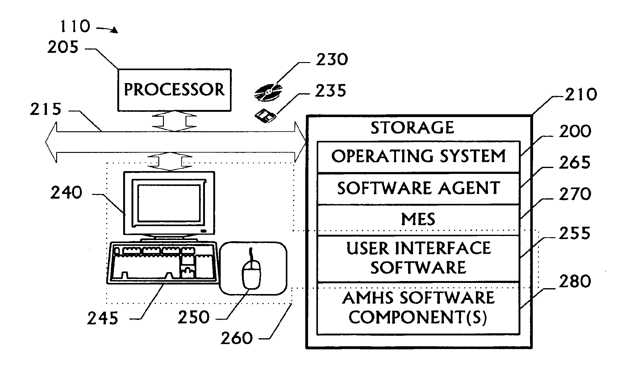
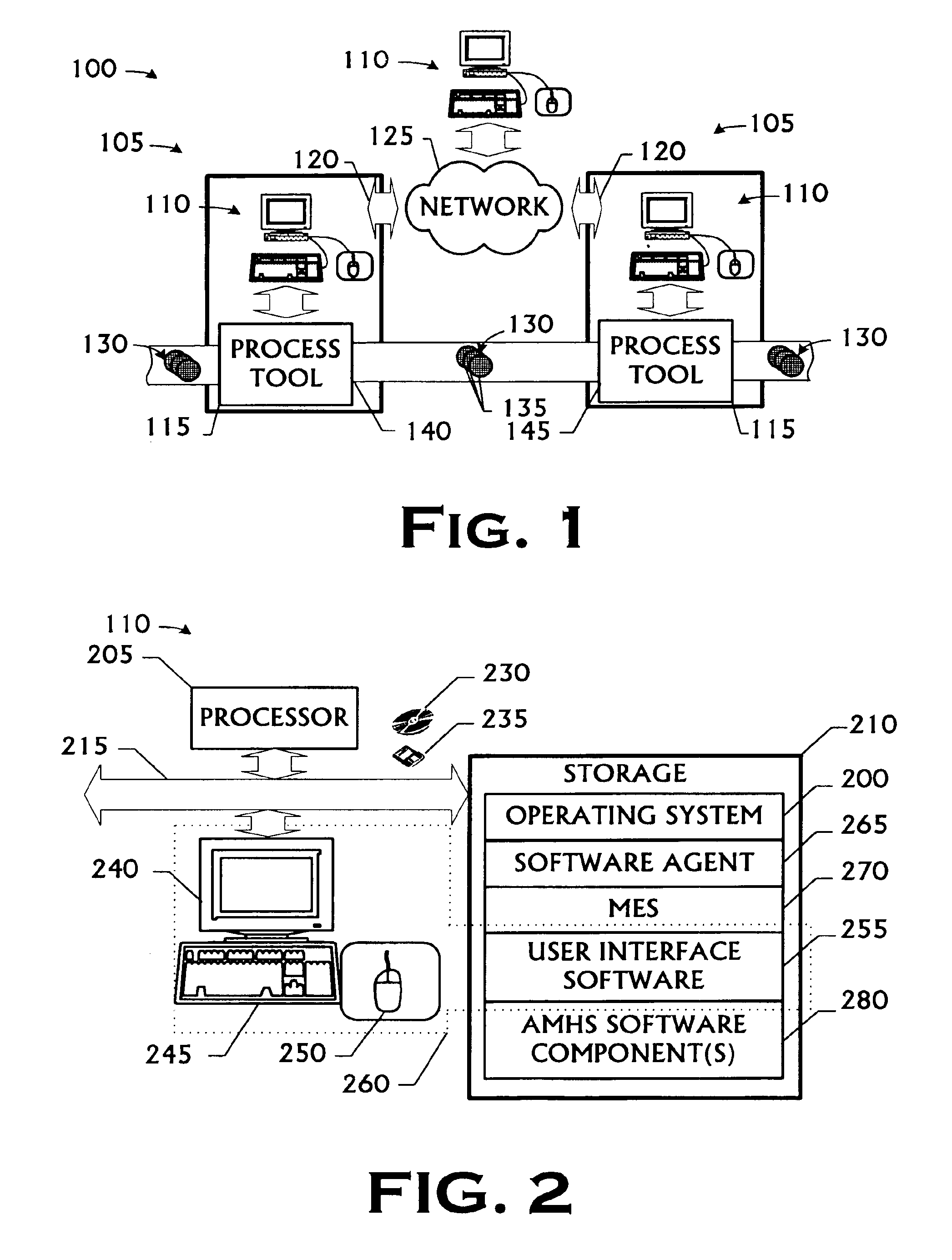
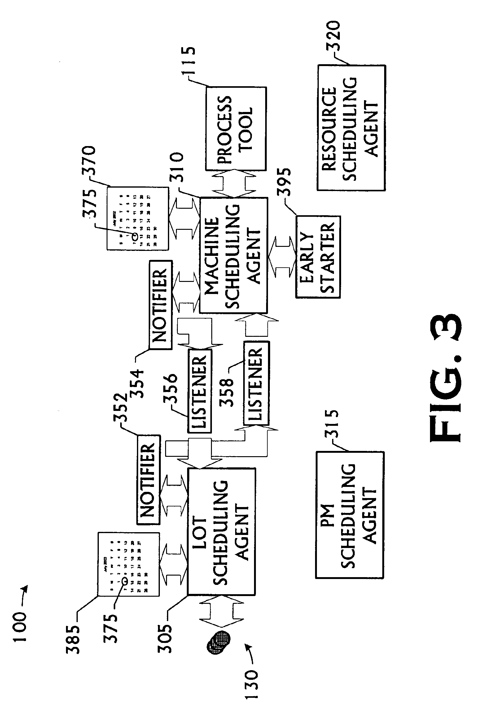
[0031]FIG. 1 conceptually illustrates a portion of one particular embodiment of a process flow 100 constructed and operated in accordance with the present invention. The process flow 100 fabricates semiconductor devices. However, the invention may be applied to other types of manufacturing proces...


PUM


Abstract

A method and apparatus for scheduling in an automated manufacturing environment, comprising are disclosed. The method includes detecting an occurrence of a predetermined event in a process flow; notifying a software scheduling agent of the occurrence; and reactively scheduling an action from the software scheduling agent responsive to the detection of the predetermined event. The apparatus is automated manufacturing environment including a process flow and a computing system. The computing system further includes a plurality of software scheduling agents residing thereon, the software scheduling agents being capable of reactively scheduling appointments for activities in the process flow responsive to a plurality of predetermined events.

Description

[0001]The United States Government has a paid-up license in this invention and the right in limited circumstances to require the patent owner to license others on reasonable terms as provided for by the terms of Award No. 70NANB7H3041 awarded by the United States Department of Commerce, National Institute of Standards and Technology (“NIST”).BACKGROUND OF THE INVENTION[0002]1. Field of the Invention[0003]This invention pertains to automated manufacturing environments, and, more particularly, to scheduling in an automated manufacturing environment.[0004]2. Description of the Related Art[0005]Growing technological requirements and the worldwide acceptance of sophisticated electronic devices have created an unprecedented demand for large-scale, complex, integrated circuits. Competition in the semiconductor industry requires that products be designed, manufactured, and marketed in the most efficient manner possible. This requires improvements in fabrication technology to keep pace with ...

Claims


Application Information

Patent Timeline
Patent Type & Authority Patents(United States)
IPC IPC(8): G05B19/418G06Q10/06
CPCG06Q10/06312G05B19/41865Y02P90/02Y02P90/80G05B19/418
Inventor MATA, GUSTAVONETTLES, STEVEN C.BARTO, LARRY D.LI, YIWEI
Owner OCEAN SEMICON LLC
Learn More