Liquid crystal display device and inspection method for a transparent substrate

Active Publication Date: 2005-06-14
OPTREX CORP +1
View PDF8 Cites 4 Cited by
  • Summary
  • Abstract
  • Description
  • Claims
  • Application Information

AI Technical Summary

Benefits of technology

[0013]Further, in the production of a transparent substrate such as a glass substrate or the like, it is preferred that it is possible to confirm easily unevenness in the thickness of the transparent substrate.
[0015]Further, it is an object of the present invention to provide an inspection method for a transparent substrate, capable of confirming easily unevenness in the thickness of a transparent substrate.

Problems solved by technology

However, the improvement of yield was difficult because the cause of the generation of the line-shaped ununiformity of brightness in the display screen due to the leakage of light was unclear.

Method used


Image

  • Liquid crystal display device and inspection method for a transparent substrate
  • Liquid crystal display device and inspection method for a transparent substrate
  • Liquid crystal display device and inspection method for a transparent substrate

Examples


example 1

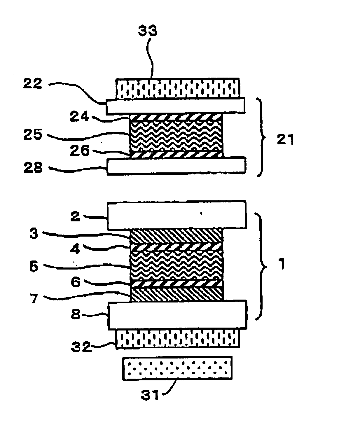
[0132]A displaying cell was prepared in a manner as follows. A transparent electrode is disposed on each of two glass substrates of 0.7 mm thick, and an alignment film was formed on each of the transparent electrodes. A rubbing treatment was conducted to alignment films. In the rubbing treatment, the direction of rubbing was determined so as to form a twist angle of 180° in a state that the two glass substrates were combined by interposing liquid crystal therebetween. After the rubbing, the glass substrates were piled up so that the transparent electrodes each having the alignment film oppose to each other and liquid crystal was injected between the glass substrates in a shield state. As the liquid crystal, a commercially available liquid crystal (“ZLI4431”: Δn=0.1643 manufactured by Merck) was used. The cell gap was 6 μm and Δn·d was 0.986 μm.

[0133]A compensation cell was prepared in a manner as follows. An alignment film was formed on each of two glass substrates of 0.55 mm thick,...

example 2

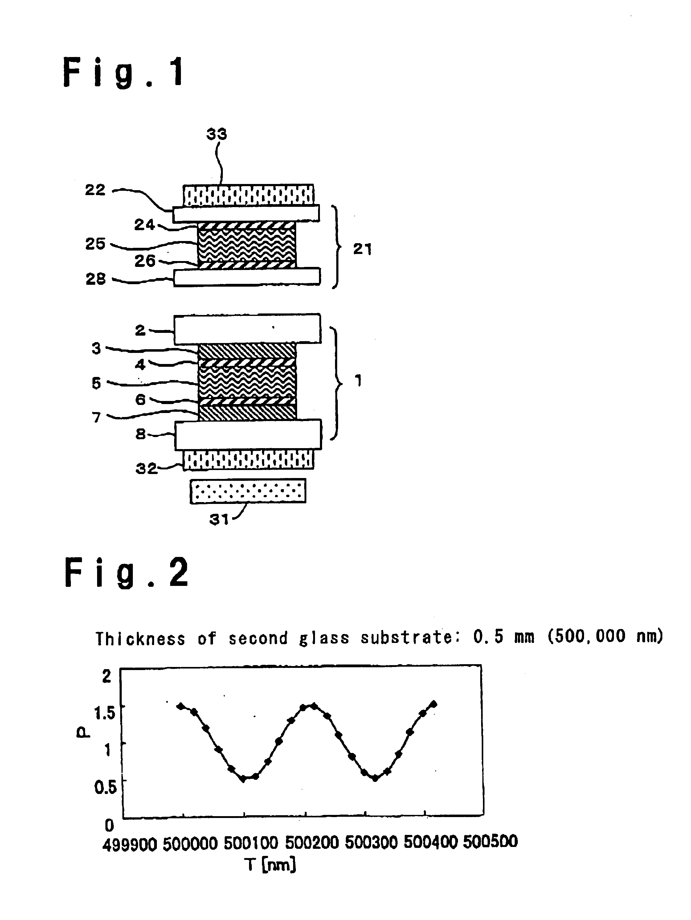
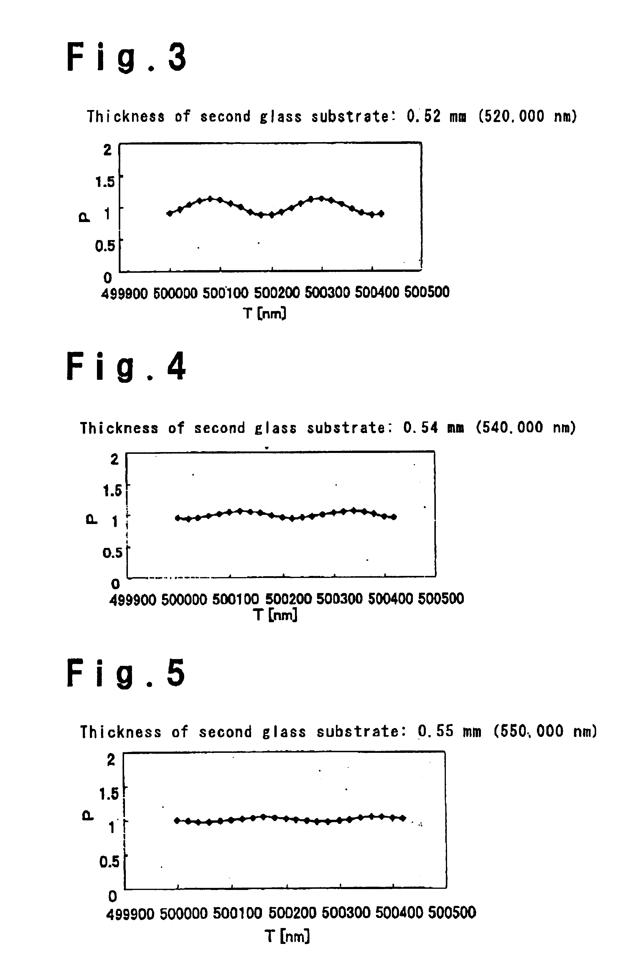
[0138]Glass substrates of 0.55 mm thick were used for the glass substrates of the displaying cell, and glass substrates of 0.5 mm thick were used as the glass substrates of the compensation cell. Then, a liquid crystal display device was prepared in the same manner as Example 1. The difference of thickness between adjacent glass substrates in the displaying cell and the compensation cell is 0.05 mm. A display of good dark appearance was obtained without generating a line-shaped ununiformity of brightness in a case that no voltage was applied to the liquid crystal layer of the displaying cell.

example 3

[0139]A glass substrate of 0.55 mm thick was used as the glass substrate at a front surface side of the displaying cell, and a glass substrate of 0.5 mm thick was used as the glass substrate at a rear surface side of the displaying cell. Further, glass substrates of 0.5 mm thick were used for the glass substrates of the compensation cell. Then, a liquid crystal display device was prepared in the same manner as Example 1. The difference of thickness between adjacent glass substrates in the displaying cell and the compensation cell is 0.05 mm. A display of good dark appearance could be obtained without generating a line-shaped ununiformity of brightness in a case that no voltage was applied to the liquid crystal layer of the displaying cell.

[0140]A liquid crystal display device was prepared in the same manner as comparative Example 1 except that glass substrates of 0.55 mm thick were used for the glass substrates of the displaying cell and the glass substrates of the compensation cell...


PUM


Abstract

A liquid display device of D-STN mode capable of suppressing a line-shaped ununiformity of brightness in displaying a dark appearance is presented. A displaying cell 1 and a compensation cell 21 are formed so that there is a difference of thickness of at least 0.05 mm between the thickness of a glass substrate 2 at a front side of the displaying cell 1 and the thickness of a glass substrate at a rear side of the compensation cell 21. The displaying cell 1 and the compensation cell 21 are arranged between a first polarizing plate 32 and a second polarizing plate 33. A backlight 31 is of a type emitting light whose half value width with respect to the peak luminance is at least 5 nm.

Description

BACKGROUND OF THE INVENTION[0001]1. Field of the Invention[0002]The present invention relates to a liquid crystal display device and an inspection method for a transparent substrate. The present invention relates, in particular, to a liquid crystal display device of D-STN (Double layered Super-Twisted Nematic) mode.[0003]2. Discussion of Background[0004]Various kinds of liquid crystal display device of TN (Twisted Nematic) mode, STN (Super-Twisted Nematic) mode or the like have widely been used. The liquid crystal display device of TN mode is of such a system that a nematic liquid crystal is sandwiched by two glass substrates wherein the direction of long axis of liquid crystal molecules is twisted 90° between the glass substrates. The device of STN mode is of a system that the twist angle is 180° or more in order to obtain a sharp change in the intensity of transmitting light to an applicable voltage.[0005]When a monochrome display of a light source color and a dark appearance is t...

Claims


Application Information

Patent Timeline
IPC IPC(8): G02F1/13G01B11/06G01J9/00G01N21/41G01N21/896G01N21/95G02F1/13363
CPCG01B11/0675G02F1/133636G01N21/896G02F2203/64G01N2021/9513
Inventor OZEKI, MASAOFERTIG, WERNERLAUENSTEIN, CHRISTIAN
Owner OPTREX CORP
Why Eureka
Try Eureka