
Time division multiplexed, piloted current monitoring in a switched mode DC-DC voltage converter and phase current measurement calibration for a multiphase converter

a voltage converter and multi-phase technology, applied in the direction of power supply testing, process and machine control, instruments, etc., can solve the problems of small voltages across the components of the components, high efficiency loss of the interference, and small practical problems of each element, so as to achieve accurate measurement of current flow and efficient operation

Inactive Publication Date: 2005-06-14
INTERSIL INC
View PDF5 Cites 55 Cited by
  • Summary
  • Abstract
  • Description
  • Claims
  • Application Information

AI Technical Summary

Benefits of technology

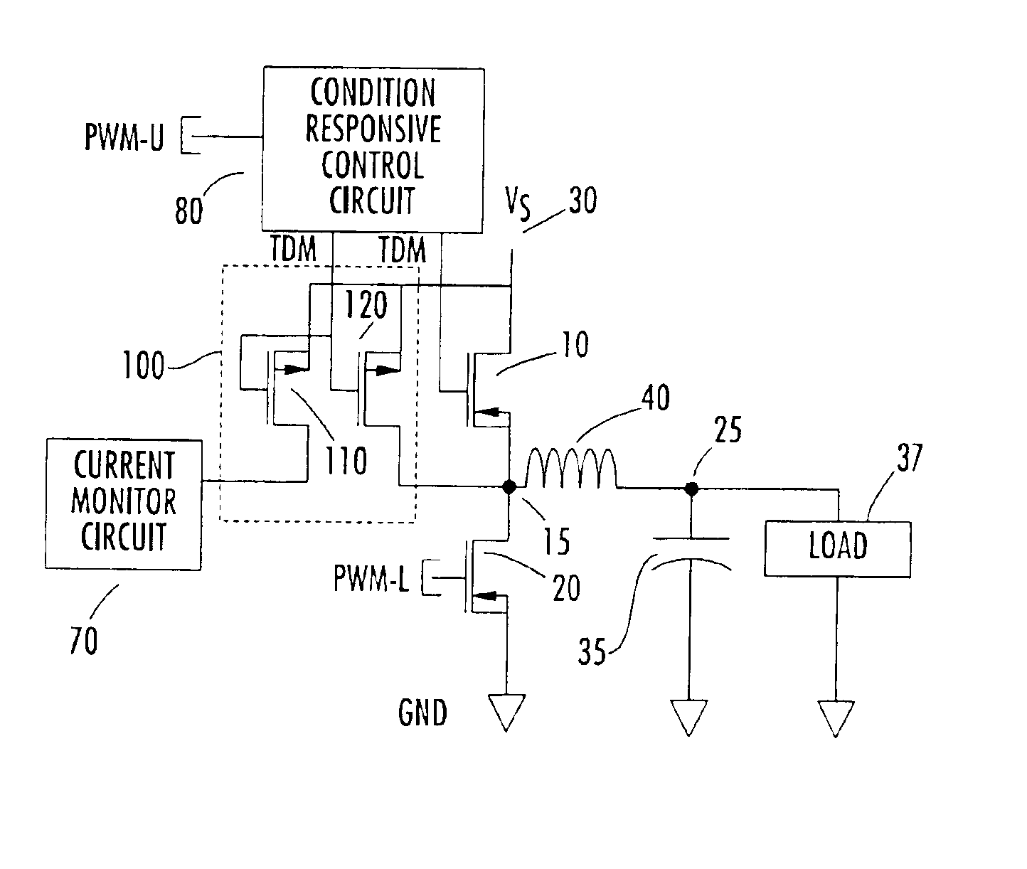
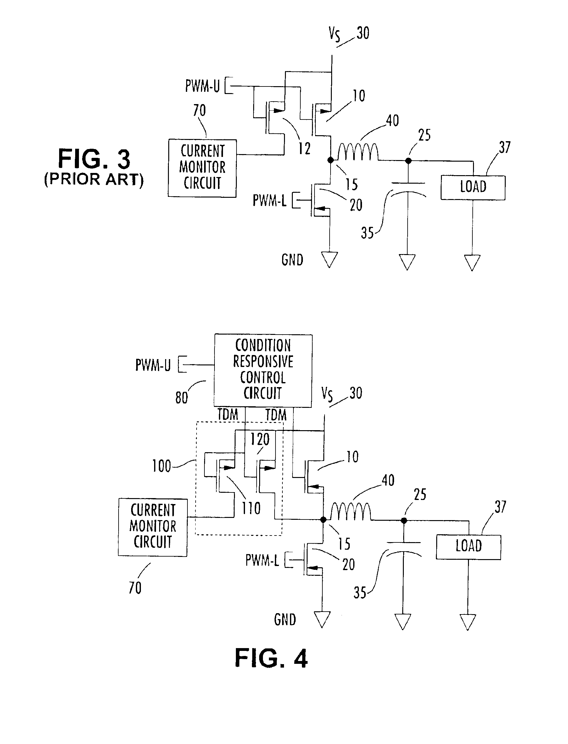
[0014]As in the architecture of FIG. 2, described above, a determination of the current flow through the auxiliary high side MOSFET is based upon the current flowing through the pilot device and the geometric ratio of the size of the pilot device to that of the high side auxiliary MOSFET. Pursuant to the invention, the pilot circuitry is activated on a reduced frequency, time division multiplexed basis relative to that of the high side MOSFET—for example, once for every 20 to 1000 cycles for the high side MOSFET. This leads to a very efficient operation, as the high side MOSFET is activated for a large number of switching cycles relative to the pilot circuitry, but the pilot circuitry is activated sufficiently often to derive a relatively accurate measure of current flow.

Problems solved by technology

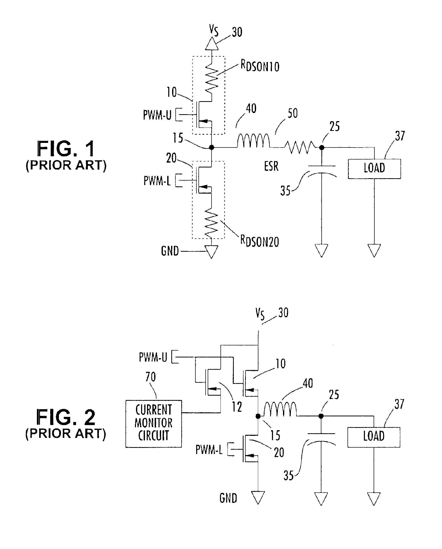
Accurate measurement of current in a half-bridge phase of a buck mode DC-DC voltage converter, a reduced complexity diagram of which is shown in FIG. 1, has become a fundamental design issue in many CPU core power applications.
This effectively corresponds to a DC output impedance that would represent a much too high efficiency loss, if it were actually implemented with an output resistor.
Although use may be made of only the above-referenced parasitic resistances of the half-bridge obtaining indirect measurement of the inductor current, each element has practical problems associated with it.
Moreover, in all cases, if the converter is efficient, the voltages across these components are small so that noise is a concern.
This requirement entails the difficulty of avoiding switching transients in the RDSON waveform.
However, doing so would introduce additional power dissipation losses and extra components in the design.
A principal disadvantage of this architecture is the necessity of using a specialized MOSFET (comprised of the combination of the high side MOSFET and its associated pilot device).
A disadvantage is the reduced performance of PMOS device compared with an NMOS device.
Also a PMOS device is more costly and requires more gate drive than a comparable NMOS device.
However, this leads to a very expensive power transistor, when compared to using a discrete MOSFET.
As a result, conventional piloted current measurement designs require a tradeoff between significant price (associated with cost of production) and performance.

Method used


Image

  • Time division multiplexed, piloted current monitoring in a switched mode DC-DC voltage converter and phase current measurement calibration for a multiphase converter
  • Time division multiplexed, piloted current monitoring in a switched mode DC-DC voltage converter and phase current measurement calibration for a multiphase converter
  • Time division multiplexed, piloted current monitoring in a switched mode DC-DC voltage converter and phase current measurement calibration for a multiphase converter

Examples


Embodiment Construction

[0023]A non-limiting, but preferred embodiment of the time-division multiplexed piloted half-bridge architecture of the present invention is diagrammatically illustrated in FIG. 4 as comprising an auxiliary high side switching circuit 100 containing a pair of PMOSFETs 110 and 120 that are coupled with the high side NMOSFET 10. In particular, the auxiliary circuitry 100 comprises an integrated circuit containing relatively small area pilot (current mirror) PMOSFET 110 and a companion larger area PMOSFET 120. For this purpose, the larger area PMOSFET 120 may comprise a relatively large number of parallel connected PMOSFETs, the area of an individual one of which corresponds to the area of the current mirror PMOSFET 110 to realize a prescribed scaling of the current by the ratio of the areas of the two devices. In addition, while the conductance of the PMOSFET 120 could be made proximate to that of the high side NMOSFET 10, it is preferably only a fraction (e.g., one-fourth) of the sam...


PUM


Abstract

An arrangement for measuring current through a phase section of a buck mode DC-DC converter includes an auxiliary integrated circuit containing an auxiliary power MOSFET and a pilot MOSFET coupled in parallel with a current path through a high side MOSFET of a half-bridge of the converter. The pilot MOSFET has a current path coupled to a current measurement terminal. The MOSFETs of the auxiliary circuit are time division multiplexed with the high side MOSFET, whereby a determination of current through the auxiliary high side MOSFET is based upon current through the pilot device and the geometric ratio of the size of the pilot device to that of the high side auxiliary MOSFET. The high side MOSFET is activated for a large number of switching cycles relative to the pilot circuitry, but the pilot circuitry is activated sufficiently often to derive a relatively accurate measure of current flow.

Description

CROSS-REFERENCE TO RELATED APPLICATIONS[0001]The present application claims the benefit of now abandoned U.S. Provisional Applications, Ser. No. 60 / 459,668 filed Apr. 2, 2003 by L. Pearce, entitled: “Time Division Piloted Current Monitoring In Switching DC-DC Converters,” and Ser. No. 60 / 459,676, filed Apr. 2, 2003, by W. Bartlett, entitled: “Phase Current Measurement Calibration,” each application being assigned to the assignee of the present application and the disclosures of which are incorporated herein.FIELD OF THE INVENTION[0002]The present invention relates in general to DC power supplies and components therefor, and is particularly directed to a new and improved current measurement and calibration architecture for a half-bridge phase of a buck mode DC-DC voltage converter.BACKGROUND OF THE INVENTION[0003]Accurate measurement of current in a half-bridge phase of a buck mode DC-DC voltage converter, a reduced complexity diagram of which is shown in FIG. 1, has become a fundame...

Claims


Application Information

Patent Timeline
Patent Type & Authority Patents(United States)
IPC IPC(8): H02M3/158H02M3/04G01R31/40
CPCH02M3/1588G01R31/40Y02B70/1466H02M2001/0009H02M1/0009Y02B70/10
Inventor PEARCE, LAWRENCE GEORGEBARTLETT, WILLIAM DAVID
Owner INTERSIL INC
Learn More