
Method for communicating a magnetic resonance signal, and reception arrangement and magnetic resonance system operable in accord therewith

a magnetic resonance signal and receiver technology, applied in the field of communication of magnetic resonance signals, can solve the problems of cable and plug connection requirements, limit the dependability of the surface, and limit the ease of operation

Inactive Publication Date: 2005-06-14
SIEMENS HEATHCARE GMBH
View PDF4 Cites 39 Cited by
  • Summary
  • Abstract
  • Description
  • Claims
  • Application Information

AI Technical Summary

Benefits of technology

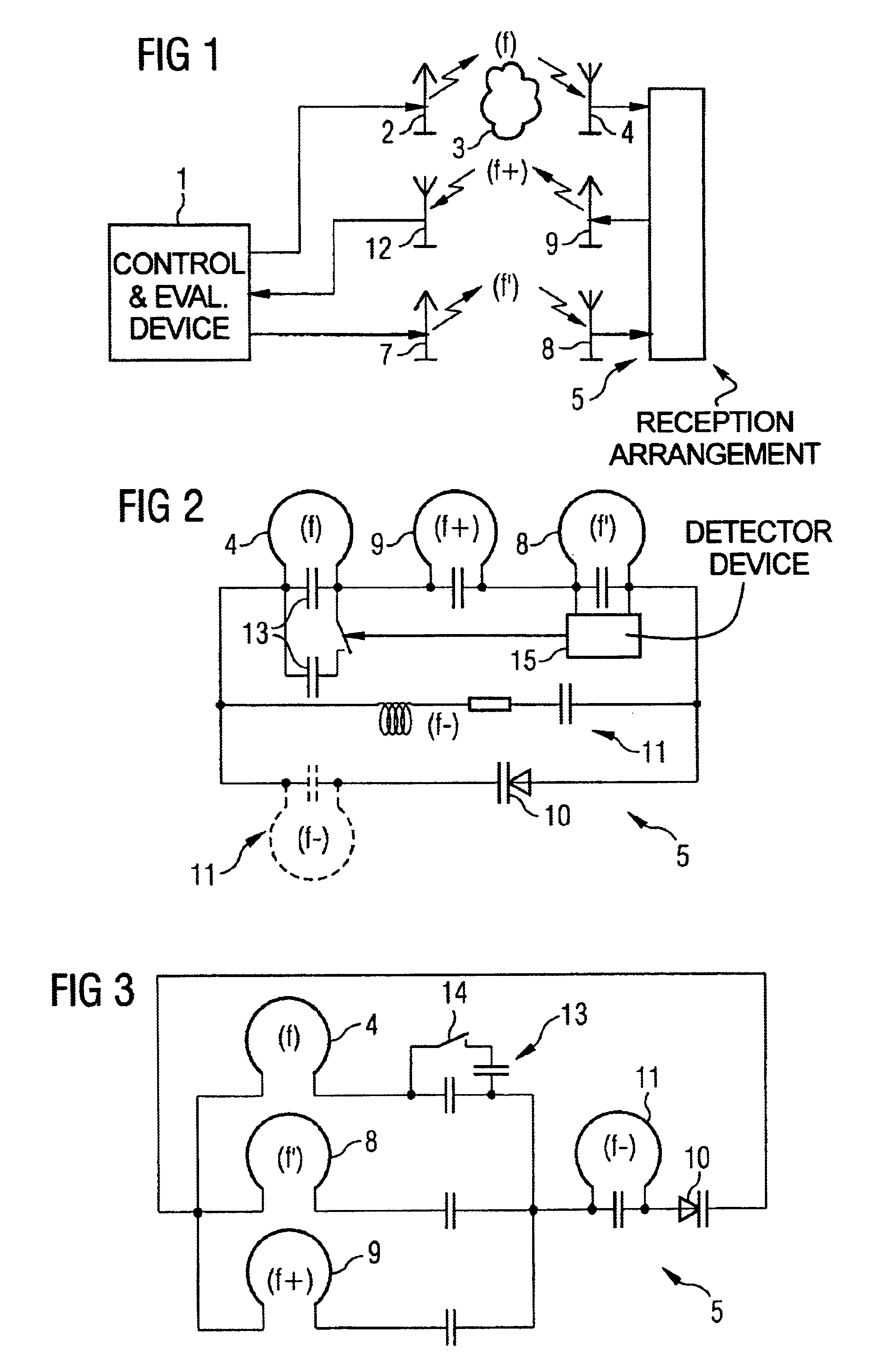
[0007]An object of the present invention is to provide a communication method for a magnetic resonance signal, and a reception arrangement and a magnetic resonance system operable in accordance with the method, with which a wireless communication of the magnetic resonance signal to the evaluation device is possible without energy sources and oscillators being structurally allocated to the reception arrangement.

Problems solved by technology

The cable and the required plug connections, however, represent a limitation on the ease of operation and on the dependability of the surface coil and the corresponding signal transmission.

Method used


Image

  • Method for communicating a magnetic resonance signal, and reception arrangement and magnetic resonance system operable in accord therewith
  • Method for communicating a magnetic resonance signal, and reception arrangement and magnetic resonance system operable in accord therewith
  • Method for communicating a magnetic resonance signal, and reception arrangement and magnetic resonance system operable in accord therewith

Examples


Embodiment Construction

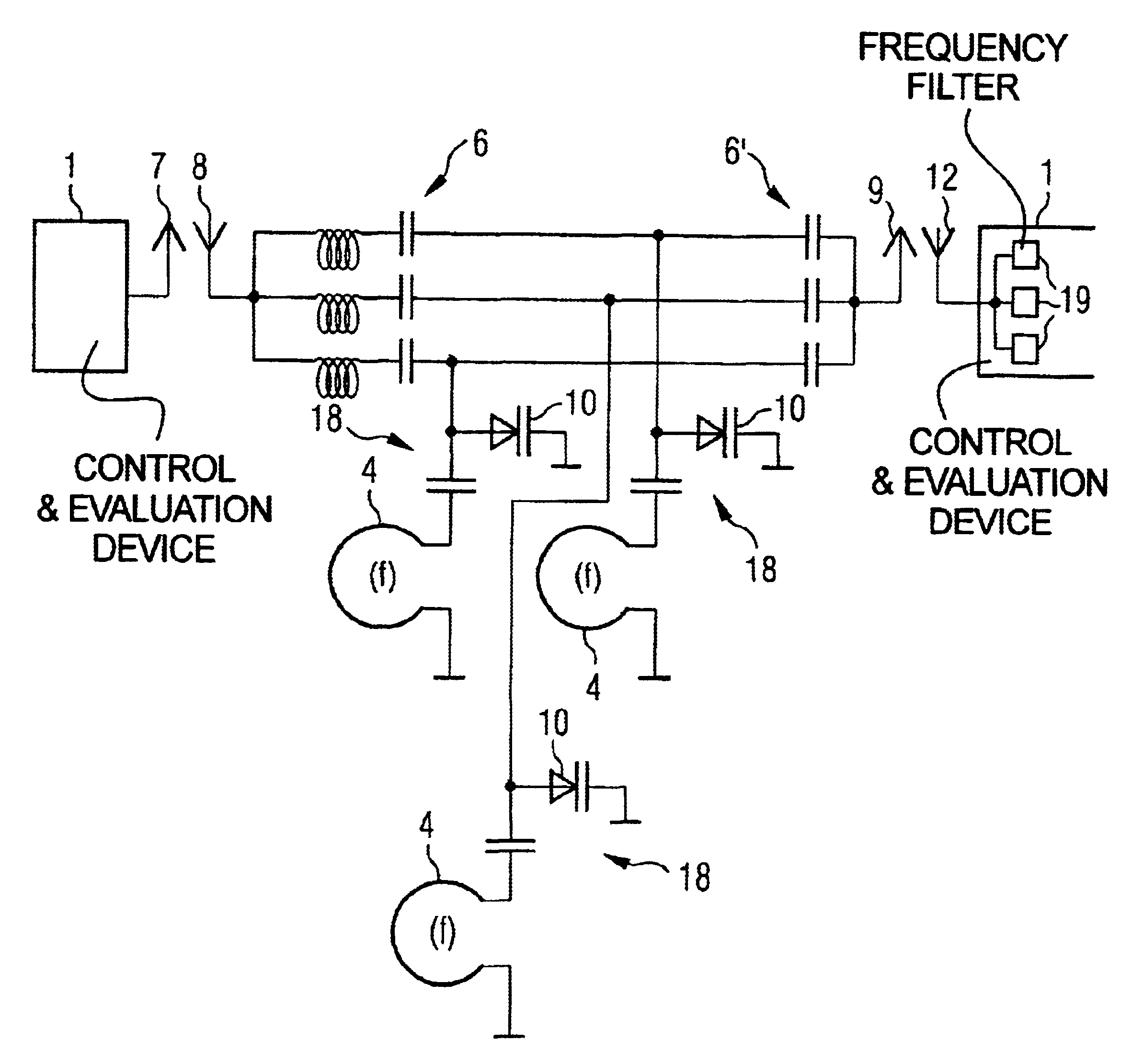
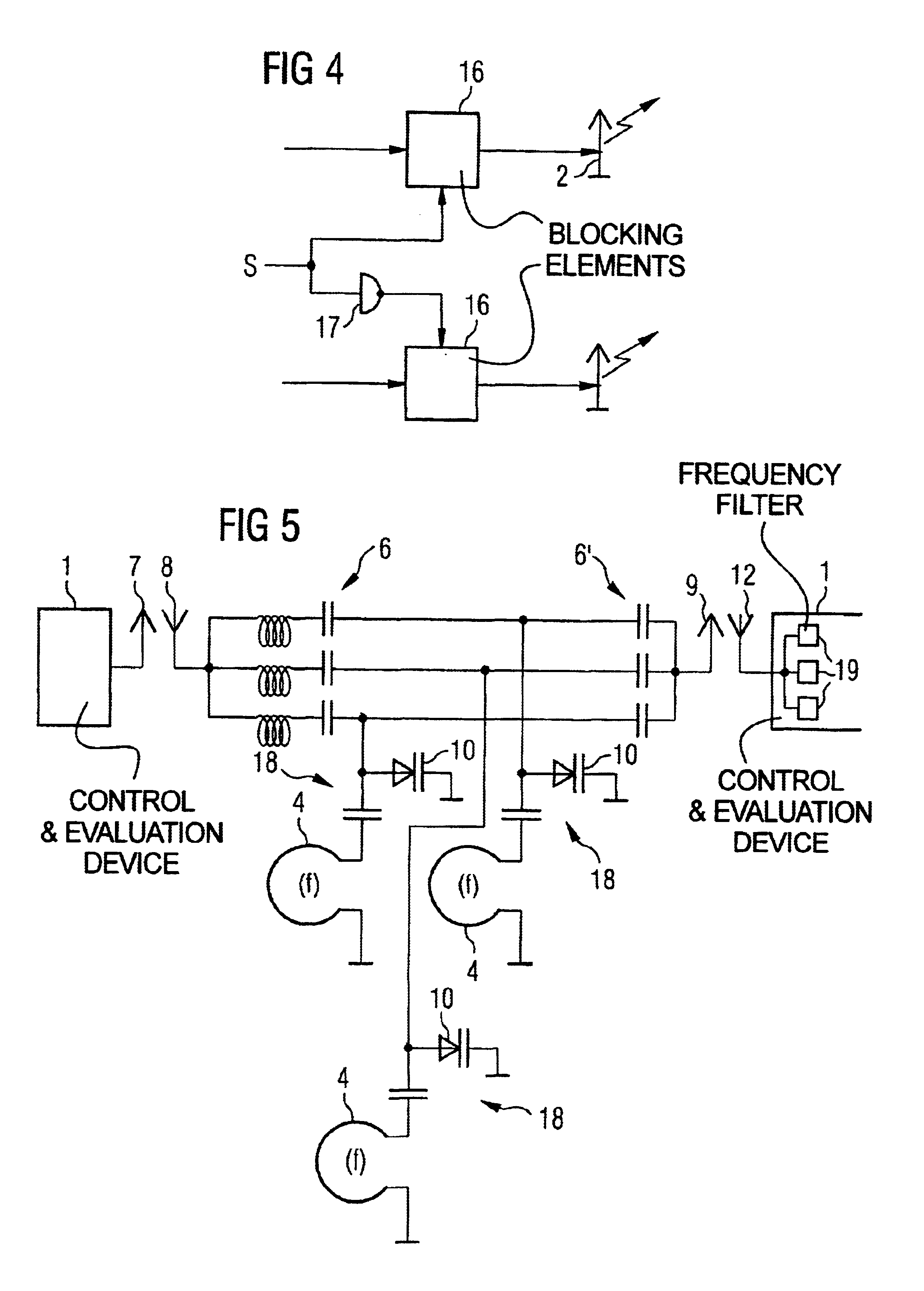
[0020]As shown in FIGS. 1 and 2, a magnetic resonance system has a control and evaluation device 1. Among other things, the control and evaluation device 1 drives a magnetic resonance transmission antenna 2, so that it emits a magnetic resonance excitation signal with a magnetic resonance frequency f. Nuclear spins in an examination subject 3 (for example, a human) are excited to a resonant condition on the basis of the magnetic resonance excitation signal.

[0021]After the excitation of the spins of the examination subject 3 is complete, a magnetic resonance reception antenna 4 of a reception arrangement 5 receives a magnetic resonance signal. The received magnetic resonance signal likewise is at the magnetic resonance frequency f. The magnetic resonance reception antenna 4 forwards the received magnetic resonance signal to a non-linear reactance 10 unmodified, i.e., unamplified.

[0022]The magnetic resonance system also has an auxiliary transmission antenna 7. Auxiliary energy is emit...


PUM


Abstract

In a communication method for a magnetic resonance signal and a reception arrangement and magnetic resonance system corresponding therewith, a non-linear reactance is supplied with a magnetic resonance signal by a magnetic resonance reception antenna and with auxiliary energy by an auxiliary reception antenna. The auxiliary energy is emitted by an auxiliary transmission antenna. The non-linear reactance mixes the auxiliary energy and the magnetic resonance signal to form a mixed signal with a sum frequency and supplies it to a mixed signal transmission antenna. The latter emits at the mixed frequency. A mixed signal reception antenna receives the mixed signal and supplies it to an evaluation device.

Description

BACKGROUND OF THE INVENTION[0001]1. Field of the Invention[0002]The present invention is directed to a communication method for a magnetic resonance signal from a magnetic resonance reception antenna to an evaluation device, as well as to a reception arrangement for a magnetic resonance signal that is suitable for the implementation of this method, and to a corresponding magnetic resonance system.[0003]2. Description of the Prior Art[0004]Because of the signal-to-noise ratio that can be obtained, it is advantageous in magnetic resonance systems to employ local or surface coils. Such coils are usually connected by a cable to an evaluation device. The cable and the required plug connections, however, represent a limitation on the ease of operation and on the dependability of the surface coil and the corresponding signal transmission.[0005]It is also known to convert a received magnetic resonance signal to a different frequency and to transmit it wirelessly to the evaluation device. Au...

Claims


Application Information

Patent Timeline
IPC IPC(8): G01R33/32G01R33/36
CPCH03F7/04G01R33/3692
Inventor HEID, OLIVERVESTER, MARKUS
Owner SIEMENS HEATHCARE GMBH
Learn More