
Baseball bat with replaceable barrel

a bat and barrel technology, applied in the field of softball bats, can solve the problems of difficult to achieve one of these objectives without compromising, deficient disclosures and inventions of the past, and bats may be very durable or easily susceptible to damage, and achieve the effect of quick and easy removal and replacemen

Inactive Publication Date: 2005-06-14
HOONFORSYTHE TECH
View PDF40 Cites 28 Cited by
  • Summary
  • Abstract
  • Description
  • Claims
  • Application Information

AI Technical Summary

Benefits of technology

Enables users to maintain high performance without sacrificing durability, allowing for quick and affordable adjustments to suit various playing conditions and extending the bat's lifespan by replacing damaged sections.

Problems solved by technology

The disclosures and inventions of the past are deficient in teaching the use of a bat with a barrel section that may be removed from the bat and replaced with a new section when a change in the performance characteristics of the bat is required or when the barrel section becomes damaged.
It is difficult to accomplish one of these objectives without compromising the other.
Depending upon the performance and / or durability desired, the bat may be very durable or easily susceptible to damage during play.
Higher batted ball speeds, however, put the pitcher and other infielders at some risk of being struck by a ball traveling so rapidly that they have insufficient time to react.
However, even to achieve these regulated limits, barrel walls must generally be thinned to the point that durability becomes an important issue.
This damage renders the bats of the past unsuitable for further use.
Designers have continued to struggle with the tradeoff between performance and durability.
Their solutions have been deficient in many regards.
In each case, efforts to improve the durability of the bat generally result in a reduction in performance.
Another shortcoming resulting from these approaches is an increase in the bat's weight and its polar moment of inertia, both making the bat more difficult to swing rapidly and decreasing the batter's ability to hit the ball well.

Method used


Image

  • Baseball bat with replaceable barrel
  • Baseball bat with replaceable barrel
  • Baseball bat with replaceable barrel

Examples


first embodiment

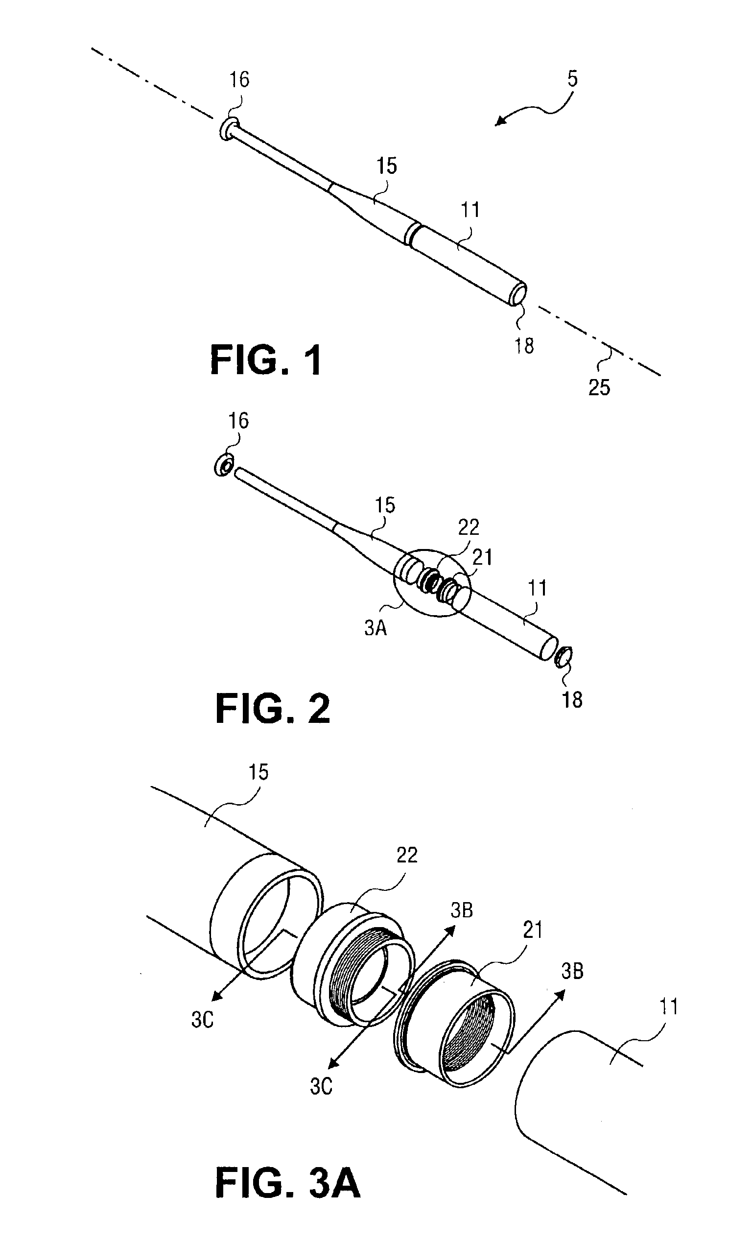
[0044]FIG. 1 is a perspective view of a bat 5 with a removable barrel 11 consisting of an integral handle and transition 15 and a barrel 11 joined together with a pair of threaded fittings (21 and 22) as shown in the exploded view of FIG. 2. The bat 5 is closed on a proximal end with a knob 16 and on the distal end with a solid end cap 18. The bat 5 is a hollow bat that behaves similarly to existing aluminum and composite bats with the exception that the barrel 11 may be separated from the integral handle and transition 15 simply by unscrewing one from the other. The knob 16 is permanently attached to the integral handle and transition 15. This can be achieved either by welding or gluing. Alternatively, the knob 16 is integrally molded with the handle 14 during manufacture. Similarly, the solid end cap 18, can be permanently attached to the barrel 11.

[0045]The barrel 11 is comprised of a hollow cylinder fabricated from metal such as aluminum or fiber reinforced composites such as gr...

second embodiment

[0050]FIG. 4 is a perspective view of a bat 35 utilizing the barrel 11 described in the embodiment of FIGS. 1-3C above. The bat 35 includes a center tube or handle 14 and a transition 12 that are different from those provided by the integral handle and transition 15. The bat 35 also includes the threaded sleeve 21, the barrel 11, the solid end cap 18, and the knob 16 similar to those described above. In this embodiment the transition 12 includes an integral male threaded flange 37 that mates with the threaded sleeve 21 to form the joint between handle 14 and barrel 11. This joint allows the barrel 11 to be easily removed and replaced by the owner. As in the previous embodiment shown in FIGS. 1-3C, the knob 16 and solid end cap 18 are permanently attached to the handle 14 and the barrel 11 respectively.

[0051]The handle 14 is preferably a hollow tube made from a metal such as aluminum or a fiber reinforced composite material such as graphite, fiberglass or aramid fibers in an epoxy, t...

third embodiment

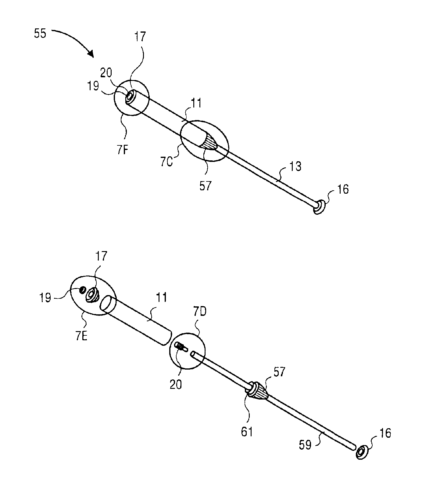
[0058]FIG. 7A is a perspective view of a reconfigurable bat 55 with a removable barrel 11 and a knob 16 similar to the barrels and knobs described for the embodiments of FIGS. 1-6B above. The bat 55 also has structurally different parts including a central tube 13, a transition 57, a hollow end cap 17, a threaded plug 20, and a nut 19. In this embodiment the joint between the transition 57 and the barrel 11 is unthreaded. Furthermore, the joint between the barrel 11 and the hollow end cap 17 is not permanent. The joining of the various parts of the bat in this embodiment is accomplished by assembling all of the components onto the central tube 13, including a nut 19 which screws onto the threaded plug 20 to secure the assembly together.

[0059]The central tube 13 is a structural element made from a metal such as aluminum, a fiber reinforced composite materials such as graphite, fiberglass or aramid fibers in an epoxy, thermoset, or thermoplastic matrix similar to the central tube or h...


PUM


Abstract

A baseball or softball bat configured to allow the removal and replacement of the barrel section of the bat if the barrel is damaged or simply for enabling selection of a barrel having particular performance characteristics. Alternatively, the barrel may be selectively changed to meet certain regulation requirements. In one aspect, one or more components of the ball bat can be provided as a kit. In another aspect, the ball bat can be made by forming and assembling the components simply and inexpensively. Exemplary embodiments include a center tube or handle, a transition, and a barrel some or all of which can be separably combined during assembly.

Description

BACKGROUND OF THE INVENTION[0001]1. Technical Field[0002]This invention generally relates to baseball and softball bats and, more particularly, to reconfigurable bats that allow for the replacement of the barrel should a different level of performance be desired or should the barrel become damaged.[0003]2. Background Art[0004]The disclosures and inventions of the past are deficient in teaching the use of a bat with a barrel section that may be removed from the bat and replaced with a new section when a change in the performance characteristics of the bat is required or when the barrel section becomes damaged. Rather, the approaches of the past address the issues of performance and durability by trading-off one against the other in an attempt to achieve a balance which the user might appreciate.[0005]On the contrary, the designers of baseball and softball bats have had as a primary object, a bat that can hit a ball long distances. Designers have as a secondary object a bat which is d...

Claims


Application Information

Patent Timeline
Patent Type & Authority Patents(United States)
IPC IPC(8): A63B59/06A63B59/00
CPCA63B59/06A63B2102/18A63B59/50A63B2102/182
Inventor FORSYTHE, PAUL D.HOON, DOUGLAS M.
Owner HOONFORSYTHE TECH
Learn More