
Locking case

a locking case and knife technology, applied in the field of knives, can solve the problems of inconvenient top sliding mechanism, time-consuming and/or inconvenient, and inability to enable the user to place the knife blade in different positions, so as to increase the safety and accuracy of cutting, quick and easy removal and replacement of the knife blade, and easy to turn on the light

Inactive Publication Date: 2009-02-12
POMERANTZ JOSEPH L
View PDF0 Cites 10 Cited by
  • Summary
  • Abstract
  • Description
  • Claims
  • Application Information

AI Technical Summary

Benefits of technology

[0008]In another embodiment, a release mechanism for a sliding utility knife includes a two-pronged lever that releases the knife blade when pressed by the user and locks the knife blade when released. The lever has a taller prong and a shorter prong at the end of the lever. By pushing down on the taller prong, the shorter prong depresses sufficiently to allow the blade to be moved in and out of the holder. When the taller prong is released, tension in the lever brings both prongs up. As a result, if one or more grooves in the knife lines up with the shorter prong, the shorter prong positions itself within a groove to “lock” or secure the knife blade in the holder. Thus, this simple release mechanism enables the user to quickly and easily remove and replace the knife blade.
[0009]In another embodiment, the utility knife has a light, such as an LED, located beneath the knife blade, where the light is directed to a cutting area of the knife. Thus, when activated, the light allows the user to see the cutting area, providing advantages such as night time use and increased safety and accuracy in cutting. A pressure switch or button located on the bottom of the knife body activates the light when the switch is depressed and deactivates the light when the switch is released. The location of the switch enables the user to easily turn on the light when grasping the knife for use.
[0010]Due in part to one or more of these features, the utility knife of the present invention can be desirably more compact than conventional knives. For example, the utility knife can be shorter than conventional utility knives and may be up to 50% or more thinner than conventional knives.

Problems solved by technology

However, these slide mechanisms may not enable the user to place the knife blade in different positions (i.e., locked either in a completely open or completely closed position).
Another disadvantage is that a top sliding mechanism may not be convenient for some users due to placement.
This can be time-consuming and / or inconvenient.

Method used


Image

  • Locking case
  • Locking case
  • Locking case

Examples


Embodiment Construction

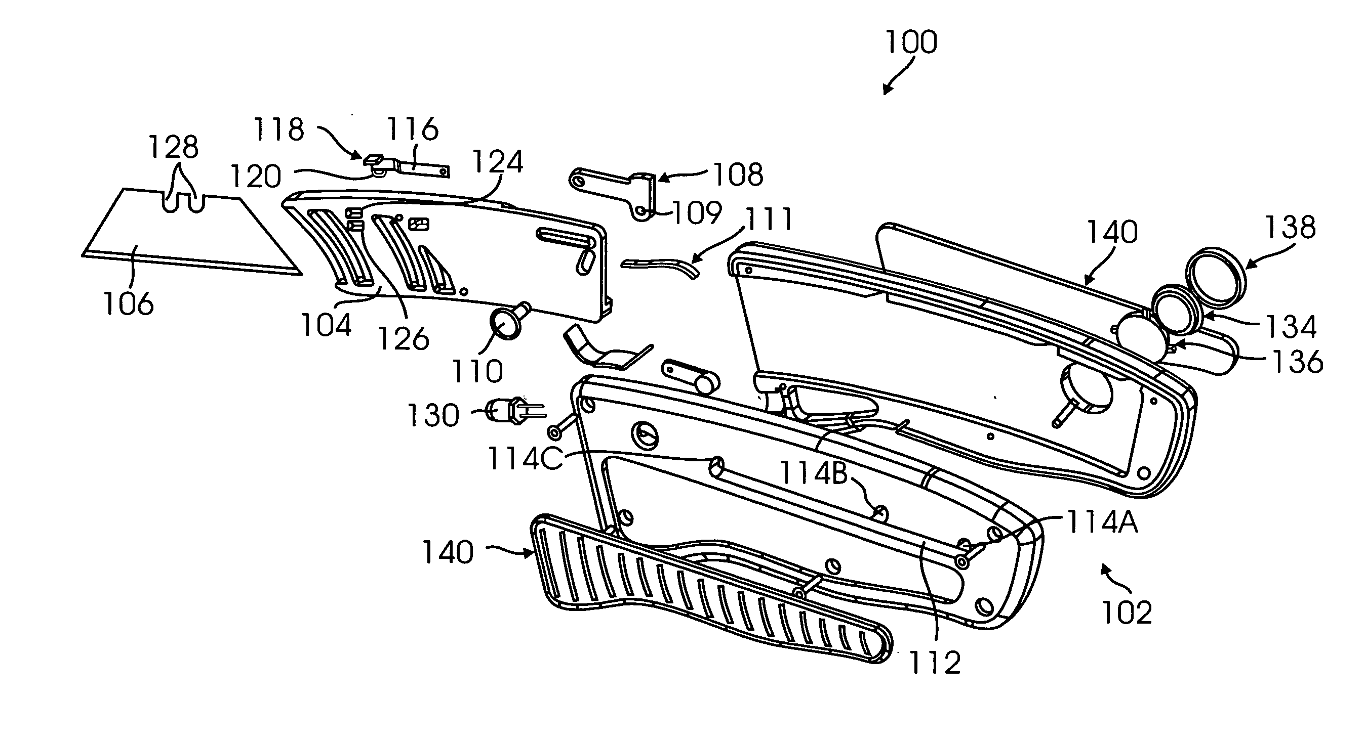
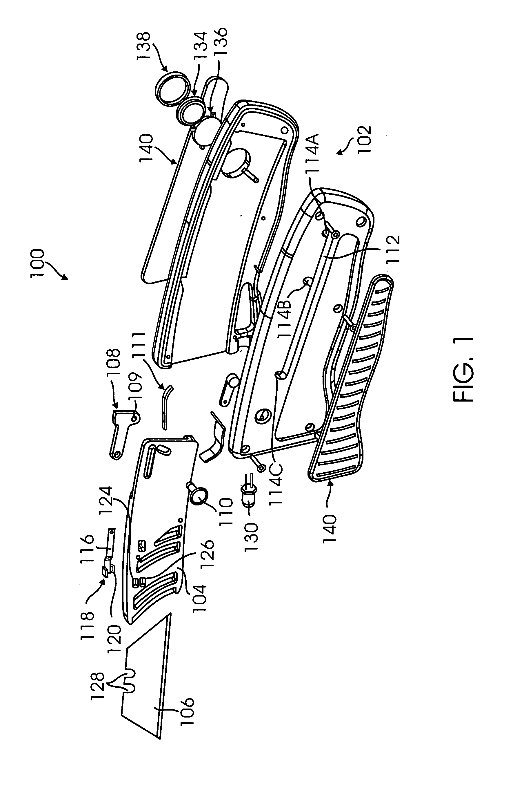
[0017]FIG. 1 is an exploded view of a utility knife 100 according to one embodiment of the present invention, and FIGS. 2A-2D are a side view, another side view, a bottom view, and an end view of utility knife 100. Utility knife includes a handle or body 102, a knife blade holder or carrier 104, and a knife blade 106. Blade carrier 104 is attached to a slide mechanism 108 on the side of body 102 to enable the blade holder to be moved in and out of the body. Slide mechanism includes a thumb or finger control button 110 attached via opening 109, such that button 110 is slidable along a lengthwise opening 112 of the body. Button 110 is shown as a round element, but other shapes are likewise suitable. Button 110 also has a rubber top surface and a knurled circumference for ease of operation, i.e., less slippage when moving slide mechanism 108.

[0018]Opening 112 has three slots 114A-114C, which enables the user to lock blade holder 104 in one of three positions. Note that opening 112 can ...


PUM


Abstract

A utility knife includes a slidably retractable knife blade, which is moving into and out of the knife body by a sliding mechanism on the side of the body. The knife blade is held by a carrier and secured to the carrier by a two-pronged lever, where a shorter one of the prongs is moved within a slot in the knife blade to secure the blade. The blade is released by pressing the longer one of the prongs to move the shorter prong out of the slot. A light in the body is located below the knife blade to enable the user to illuminate a work area while using the knife.

Description

BACKGROUND[0001]1. Field of Invention[0002]The present invention relates generally to knives and in particular to utility knives.[0003]2. Related Art[0004]Utility knives typically are designed such that the blade folds into the body of the knife so that the knife can be carried or stored without risk of cutting the user. Throughout the years, many different features and designs have been used in utility knives. One typical feature is a slide mechanism for retracting and extending the knife blade. Such a slide mechanism is typically placed on the top of the knife and allows the user to push out or pull back the blade. However, these slide mechanisms may not enable the user to place the knife blade in different positions (i.e., locked either in a completely open or completely closed position). Another disadvantage is that a top sliding mechanism may not be convenient for some users due to placement.[0005]Another feature of utility knives is the release mechanism for the blade to allow...

Claims


Application Information

Patent Timeline
Patent Type & Authority Applications(United States)
IPC IPC(8): B26B1/08
CPCB26B5/00B26B11/008B26B11/00
Inventor POMERANTZ, JOSEPH L.
Owner POMERANTZ JOSEPH L
Learn More