Reconfigurable ball bat and method
a bat and a technology of a bat body, applied in the field of reconfigurable bats, can solve the problems of compromising one of these objectives, affecting the performance of the bat, and being difficult to achieve one of these objectives without compromising, etc., and achieve the effect of quick and easy removal and replacemen
- Summary
- Abstract
- Description
- Claims
- Application Information
AI Technical Summary
Benefits of technology
Problems solved by technology
Method used
Image
Examples
first embodiment
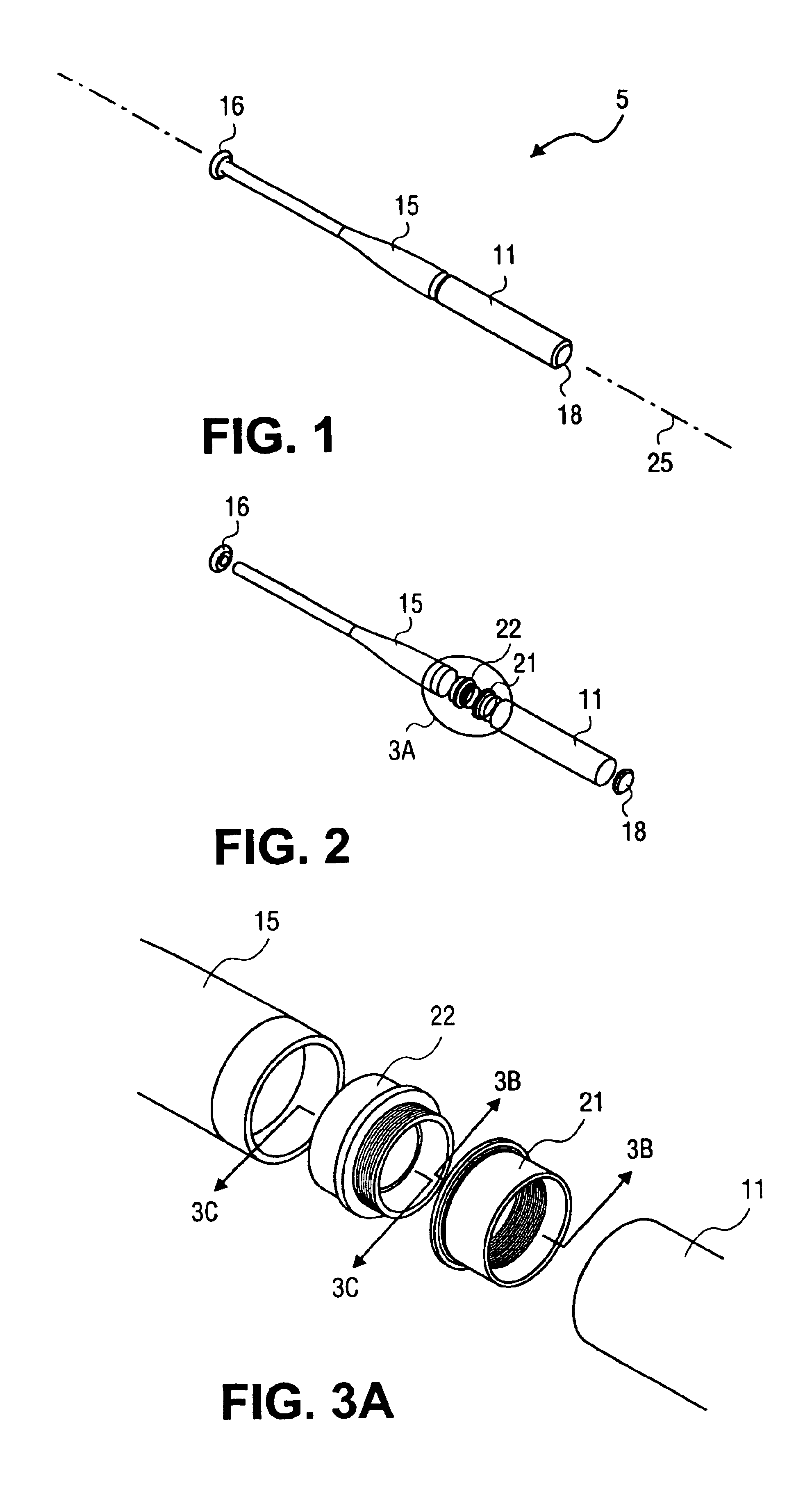
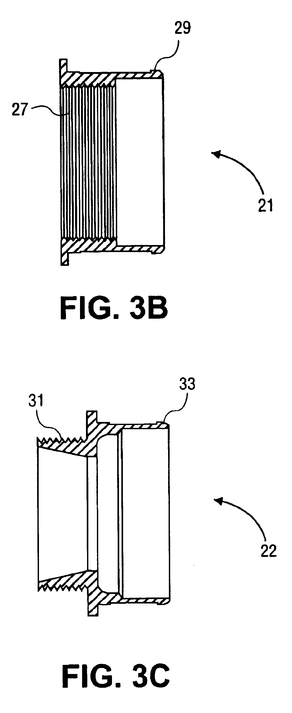
FIG. 1 is a perspective view of a bat 5 with a removable barrel 11 consisting of an integral handle and transition 15 and a barrel 11 joined together with a pair of threaded fittings (21 and 22) as shown in the exploded view of FIG. 2. The bat 5 is closed on a proximal end with a knob 16 and on the distal end with a solid end cap 18. The bat 5 is a hollow bat that behaves similarly to existing aluminum and composite bats with the exception that the barrel 11 may be separated from the integral handle and transition 15 simply by unscrewing one from the other. The knob 16 is permanently attached to the integral handle and transition 15. This can be achieved either by welding or gluing. Alternatively, the knob 16 is integrally molded with the handle 14 during manufacture. Similarly, the solid end cap 18, can be permanently attached to the barrel 11.
The barrel 11 is comprised of a hollow cylinder fabricated from metal such as aluminum or fiber reinforced composites such as graphite fiber...
second embodiment
FIG. 4 is a perspective view of a bat 35 utilizing the barrel 11 described in the embodiment of FIGS. 1-3C above. The bat 35 includes a center tube or handle 14 and a transition 12 that are different from those provided by the integral handle and transition 15. The bat 35 also includes the threaded sleeve 21, the barrel 11, the solid end cap 18, and the knob 16 similar to those described above. In this embodiment the transition 12 includes an integral male threaded flange 37 that mates with the threaded sleeve 21 to form the joint between handle 14 and barrel 11. This joint allows the barrel 11 to be easily removed and replaced by the owner. As in the previous embodiment shown in FIGS. 1-3C, the knob 16 and solid end cap 18 are permanently attached to the handle 14 and the barrel 11 respectively.
The handle 14 is preferably a hollow tube made from a metal such as aluminum or a fiber reinforced composite material such as graphite, fiberglass or aramid fibers in an epoxy, thermoset, or...
third embodiment
FIG. 7A is a perspective view of a reconfigurable bat 55 with a removable barrel 11 and a knob 16 similar to the barrels and knobs described for the embodiments of FIGS. 1-6B above. The bat 55 also has structurally different parts including a central tube 13, a transition 57, a hollow end cap 17, a threaded plug 20, and a nut 19. In this embodiment the joint between the transition 57 and the barrel 11 is unthreaded. Furthermore, the joint between the barrel 11 and the hollow end cap 17 is not permanent. The joining of the various parts of the bat in this embodiment is accomplished by assembling all of the components onto the central tube 13, including a nut 19 which screws onto the threaded plug 20 to secure the assembly together.
The central tube 13 is a structural element made from a metal such as aluminum, a fiber reinforced composite materials such as graphite, fiberglass or aramid fibers in an epoxy, thermoset, or thermoplastic matrix similar to the central tube or handle 14 des...
PUM
 Abstract
Description
Claims
Application Information
 - R&D
- Intellectual Property
- Life Sciences
- Materials
- Tech Scout
- Unparalleled Data Quality
- Higher Quality Content
- 60% Fewer Hallucinations
Browse by: Latest US Patents, China's latest patents, Technical Efficacy Thesaurus, Application Domain, Technology Topic, Popular Technical Reports.
© 2025 PatSnap. All rights reserved.Legal|Privacy policy|Modern Slavery Act Transparency Statement|Sitemap|About US| Contact US: help@patsnap.com


