
Indirect flow measurement through a breath-operated inhaler

Inactive Publication Date: 2005-06-14
HONEYWELL INT INC
View PDF11 Cites 89 Cited by
  • Summary
  • Abstract
  • Description
  • Claims
  • Application Information

AI Technical Summary

Benefits of technology

[0009]In accordance with a feature of the present invention, a flow sensor is described that allows for indirect (separate and apart from the exhaust chamber) measurement of airflow through a breath-operated device.
[0011]The indirect airflow measurement technique can also enable closure of the device's airflow ports by incorporating a design that allows for the rotation of the mouthpiece assembly from open to closed positions relative to the inhaling device's main housing body, including a handle assembly.
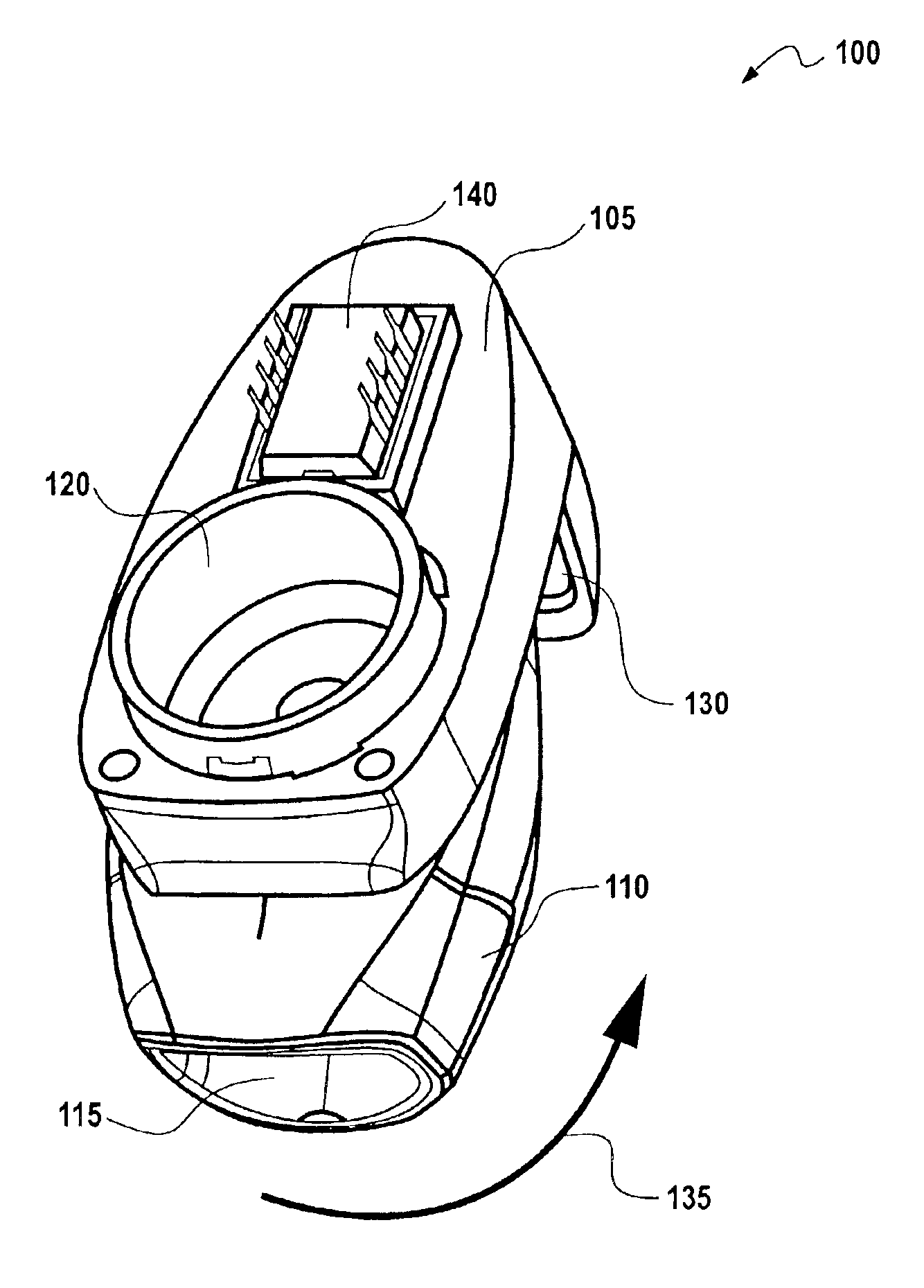
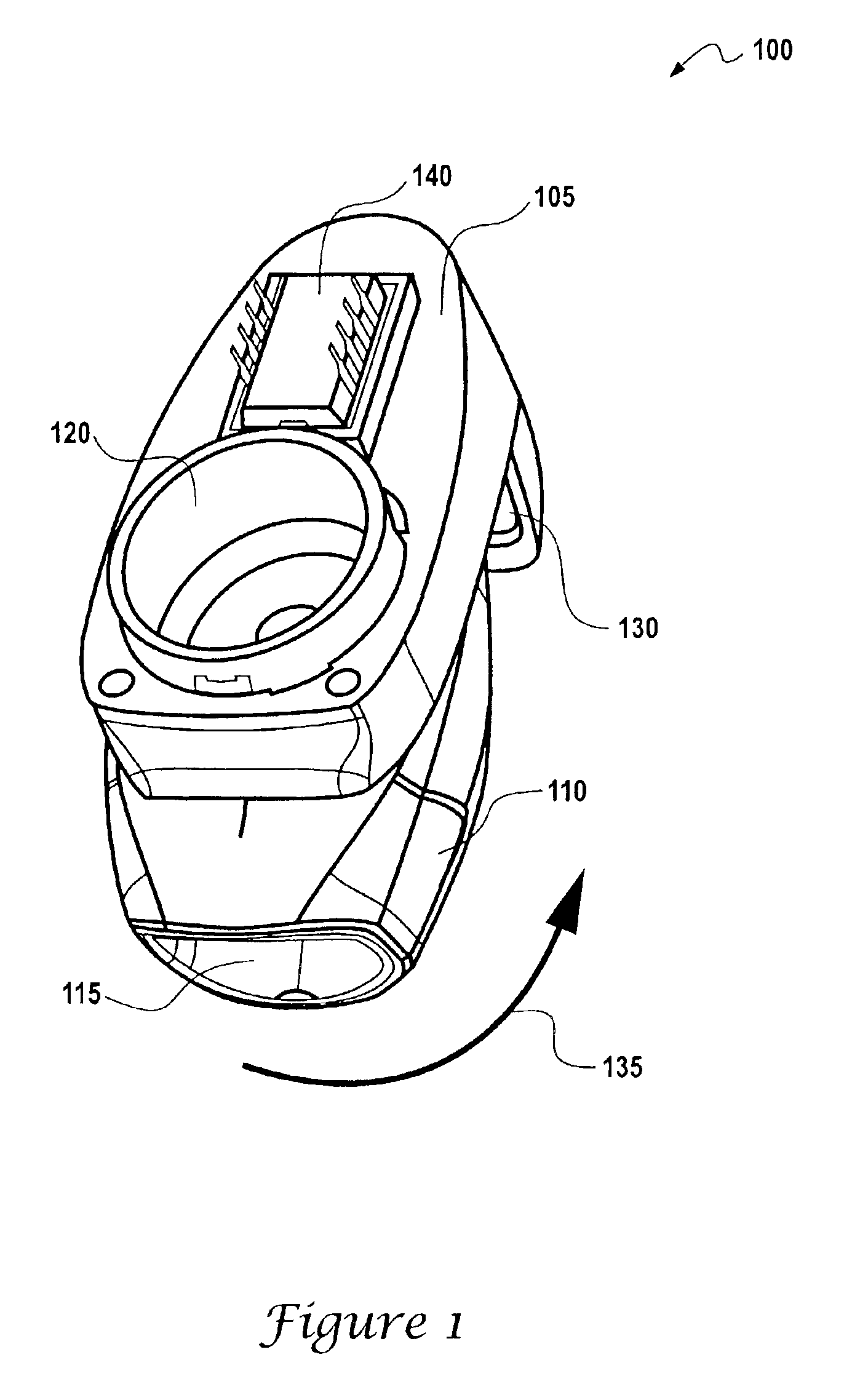
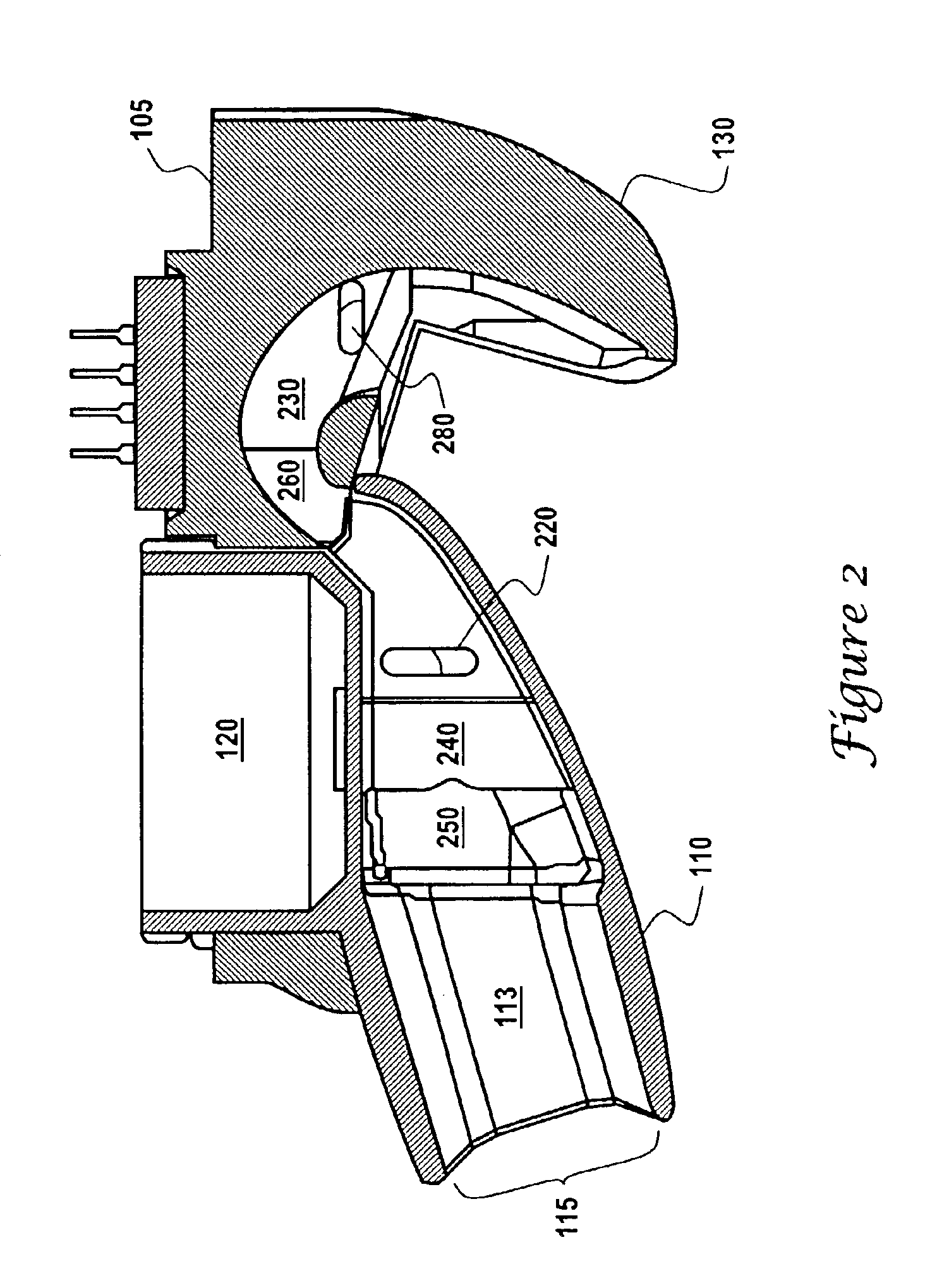
[0012]Indirect measurement of flow through a breath-operated device incorporates a flow sensor into the device and in airflow communication with a low resistance channel formed within the main body of the device together with an input port also in airflow communication with the low resistance channel. An output port is formed near the device's exhaust chamber, and preferably upstream of aerosol delivery. Both input and output ports are oriented such that the openings, which tap to the main channel, are perpendicular to the flow direction through the main channel. The output port and an aerosol delivery assembly are placed within the exhaust chamber and a low resistance channel leads from the upstream port to the sensor and then to the downstream ports. The very low-pressure drop generated by flow through the main channel mouthpiece assembly drives a small flow through the low resistance channel and across the sensor. The indirect flow measurement technique has the advantage over pressure sensor technology in that using a low resistance channel to the sensor and the high sensitivity of a thermal microsensor at low flows inherently allows it to sense very low pressure drop. A thermal microsensor can be used in the present invention to operate with low power dissipation. Furthermore, by placing the flow sensor outside the main flow path, aspects of the present invention provide for a more robust inhaling device because delicate sensing elements and wirebonds typically located within airflow sensors are physically protected.

Problems solved by technology

Difficulty arises for many patients in coordinating breathing and actuating the medicine delivery.
But with pressure sensing technology, larger diaphragms are typically needed to sense the very low pressure drop required with breath-operated devices.
As a consequence, devices with the larger size diaphragm cost more.
A flow sensor is typically deployed by placing it directly in the flow stream; but flow sensor wire bonds or sensing elements may be damaged by debris, lint, or from patient mishandling.
Hot wire anemometer flow sensors have the disadvantage of requiring relatively high power.
Although thermal microsensor type flow sensors operate with lower power, flow turbulence generated within the breath-operated device and extraneous flow in ambient air cause signal errors when placed directly in the flow.

Method used


Image

  • Indirect flow measurement through a breath-operated inhaler
  • Indirect flow measurement through a breath-operated inhaler
  • Indirect flow measurement through a breath-operated inhaler

Examples


Embodiment Construction

[0019]The novel features of the present invention will become apparent to those of skill in the art upon examination of the following detailed description of the invention or can be learned by practice of the present invention. It should be understood, however, that the detailed description of the invention and the specific examples presented, while indicating certain embodiments of the present invention, are provided for illustration purposes only because various changes and modifications within the scope of the invention will become apparent to those of skill in the art from the detailed description of the invention and claims that follow. Drawings associated with the following description provide like reference numerals that refer to identical or functionally similar elements throughout separate views and are incorporated in and form part of the specification.

[0020]Referring to FIG. 1, the flow path of a breath-operated inhaler device 100 in accordance with embodiments of the pre...


PUM


Abstract

Indirect airflow measurement through breath-operated device is accomplished by incorporating an airflow sensor into the inhaler device along a low resistance channel disposed away from the exhaust chamber of the device and having an input port in airflow communication with a low resistance channel and output input port and low resistance channel are formed in the main housing body of the device, and further incorporating an output port formed near the exhaust changer near the mouthpiece assembly, the output port also in airflow communication with the low resistance channel. A method of measuring airflow in an inhalation device is also described that measures air flowing through the low resistance channel. Another aspect of the invention provides a method that allows for the closure of the devices' airflow ports, by allowing for the rotation of the mouthpiece assembly from open to closed positions relative to the inhaling device's main housing body and towards handle assembly.

Description

TECHNICAL FIELD[0001]This invention relates to breath-operated inhaler devices. More particularly the present invention relates to providing indirect flow measurement through a breath-operated inhaler device. The present invention is also related to providing indirect flow measurement within and / or through an inhalation device by drawing air to an airflow sensor through a low resistance channel that is physically separated from the inhaler device's exhaust chamber. A method also provides for closure of the inhaler device airflow ports by allowing rotation of the mouthpiece assembly from open to closed positions relative to an inhaler device's main body and handle assembly.BACKGROUND OF THE INVENTION[0002]Devices for releasing a controlled dose of medication may be actuated electronically. Such devices are generally referred to as inhalers, inhaling devices, breath inhaling devices, and breath-operated inhaling devices. Historically, the patient actuates inhalers mechanically as he o...

Claims


Application Information

Patent Timeline
IPC IPC(8): A61M15/00A61M16/00
CPCA61M15/009A61M2016/0039
Inventor SPELDRICH, JAMIE W.MURRAY, MARTIN G.GEHMAN, RICHARD
Owner HONEYWELL INT INC
Learn More