Electro-hydraulic manifold assembly and method of making same

a technology of electrohydraulic manifolds and manifolds, applied in the direction of valve housings, non-mechanical valves, coupling device connections, etc., can solve the problems of limited space available, achieve low cost, facilitate installation, and reduce profile and volume

Inactive Publication Date: 2005-06-14
EATON CORP
View PDF15 Cites 13 Cited by
  • Summary
  • Abstract
  • Description
  • Claims
  • Application Information

AI Technical Summary

Benefits of technology

[0009]The present invention provides a unique and relatively low cost electro-hydraulic manifold assembly which is suitable for use with internal combustion engines for controlling valve enablement and disablement which has a reduced profile and volume to facilitate installation in the space between cylinder banks of a V-type engine. The manifold assembly of the present invention employs a gasket plate preferably of suitable plastic material with bosses thereon having valving cavities with solenoid operated valves received therein for, upon electrical energization of the valves, controlling flow between pressure supply ports and control pressure outlet ports associated with each boss. The valves are retained in each boss by a common mounting bracket received thereover with tabs which register against mounting lugs provided on the valve; and, the bracket, valves and gasket are secured to the manifold by suitable fasteners. The gasket has a plurality of electrical conductors embedded therein, preferably by insert molding, which terminate in a common electrical receptacle provided at the end of the gasket. The electrical terminals each have one end exposed and terminating in association with each of the valve mounting bosses found on the gasket; and, corresponding electrical terminal receptacles are provided on each valve and engage the electrical strips in plug in connection upon mounting respectively each of the valves in a boss. The electro-hydraulic manifold assembly of the present invention thus eliminates the need for a lead frame to make an electrical connection to the assembly.

Problems solved by technology

In certain engine configurations, as for example, V-type engines, the electro-hydraulic manifold is mounted between the cylinder banks where the space available is quite limited.

Method used


Image

  • Electro-hydraulic manifold assembly and method of making same
  • Electro-hydraulic manifold assembly and method of making same
  • Electro-hydraulic manifold assembly and method of making same

Examples


Embodiment Construction

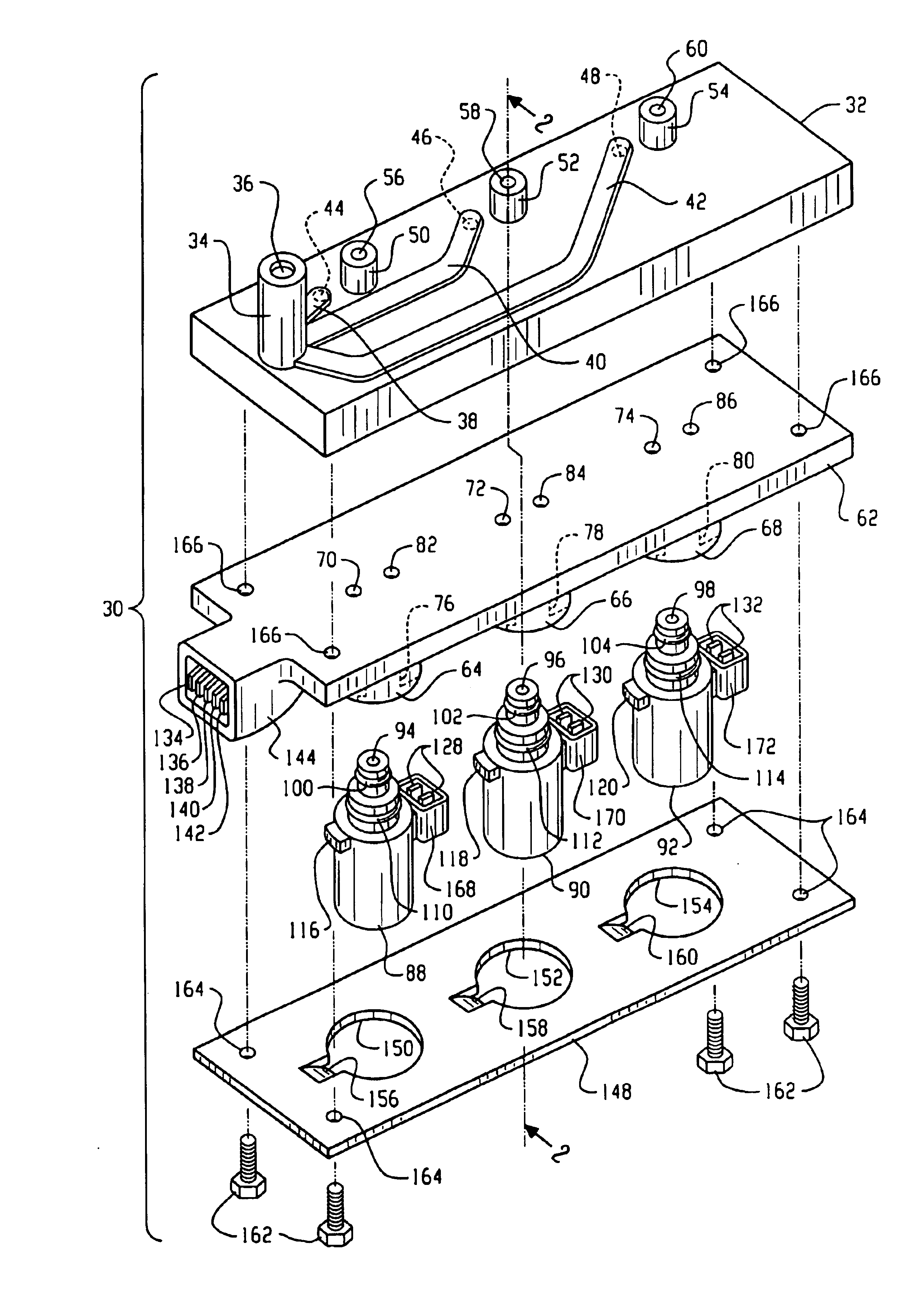
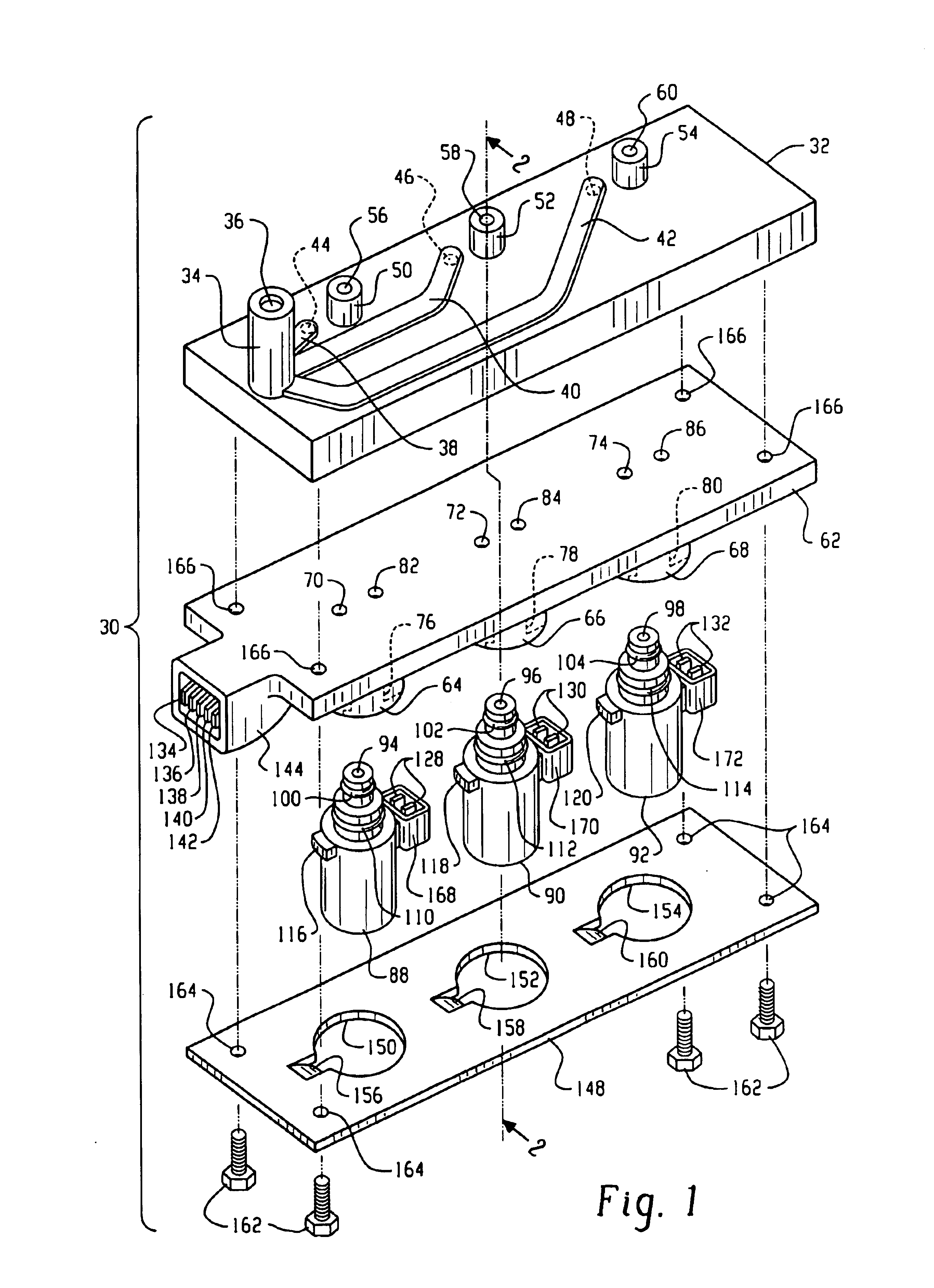
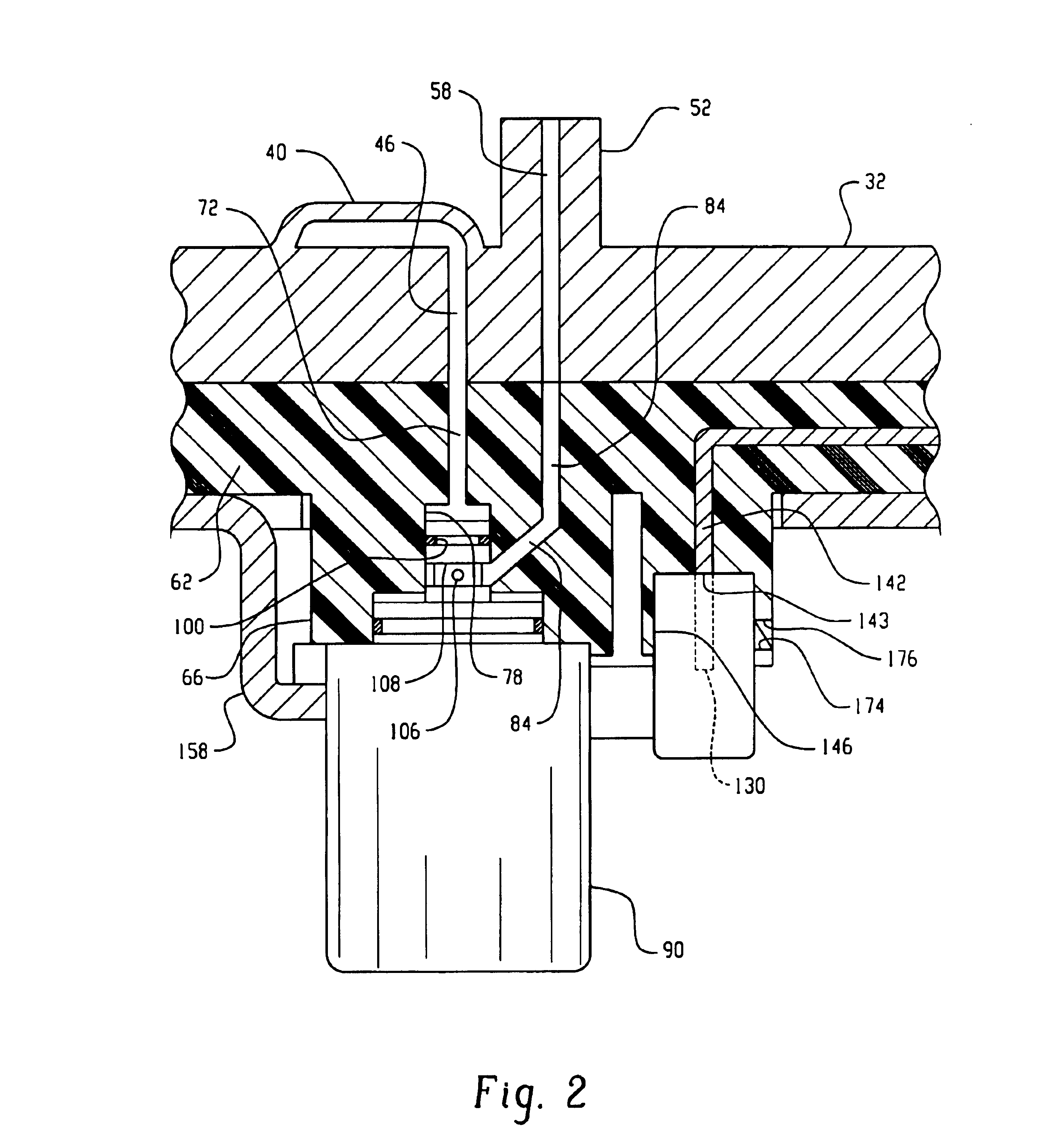
[0013]Referring to FIGS. 1 and 2, the electro-hydraulic manifold assembly of the present invention is indicated generally at 30 and includes a manifold 32 having on the upper surface thereof a boss 34 with a pressure inlet supply passage 36 formed therein which communicates with passages formed in runners 38, 40, 42 formed integrally with the manifold. Each of the runners has an internal passage (not shown) therein which communicates respectively with a supply pressure passage shown in dashed outline and denoted respectively 44, 46, 48, each of which is ported to the undersurface of the manifold.

[0014]The manifold 32 has a plurality of spaced bosses 50, 52, 54 extending outwardly therefrom, each of which has respectively a control pressure outlet passage 56, 58, 60 respectively provided therein which also passes through and is ported to the undersurface of the manifold.

[0015]The assembly 30 further includes a gasket plate 62 preferably formed of plastic material, with a plurality of...


PUM


Abstract

A manifold has a supply inlet communicating with a plurality of spaced supply ports; and, has associated with each supply port a separate control pressure passage. A gasket has a plurality of spaced bosses, each with a valving cavity with an electrically operated valve received and ported in the cavity. Each valving cavity has a supply port communicating with one of the supply ports on the manifold and a control pressure outlet port communicating with one of the control pressure passages on the manifold. A plurality of electrically conductive strips are embedded in the gasket and each is connected to a terminal pin in a receptacle shell formed on the gasket. The remote end of each of the conductor strips is exposed adjacent a valve and makes contact with a terminal on the valve when the valve is received in the respective valving cavity. A common retaining bracket is attached to the manifold and retains the valves and gasket as an assembly on the manifold.

Description

BACKGROUND OF THE INVENTION[0001]The present invention relates to manifold assemblies of the type having a plurality of electrically operated valves disposed thereon for receiving pressurized fluid from a common gallery in the manifold and, upon electrical energization, each controlling flow individually to an individual control pressure outlet for controlling a fluid pressure actuated device.[0002]Such manifolds are employed for selectively controlling the flow of fluid to hydraulic actuators, such as hydraulic lash adjusters, for enabling and disabling the opening and closing of the combustion chamber valves of an internal combustion engine. In the aforesaid combustion engine valve disablement applications, such manifold assemblies have included a manifold with supply ports for supplying each of the plurality of electrically operated valves and individual control pressure outlet ports which, upon attachment of the manifold to the engine, communicate with corresponding passages in ...

Claims


Application Information

Patent Timeline
Patent Type & Authority Patents(United States)
IPC IPC(8): F15B13/06F01L13/00F16K27/00F15B13/00F01L1/24F01L1/46F15B13/08
CPCF01L1/24F01L1/46F16K27/003F15B13/0814F15B13/0835F15B13/0857F15B13/06F01L2001/2444
Inventor MORENO, JORGE A.
Owner EATON CORP
Why Eureka
Try Eureka