
Method for controlling a power sliding van door

a technology for sliding vans and control systems, applied in doors, wing accessories, lock applications, etc., can solve the problems that the power movement of the striker from its outboard position to its inboard position cannot be sufficient to bring the door, and achieves a large force, high momentum, and high closing resistance.

Inactive Publication Date: 2005-06-14
VALEO ELECTRICAL SYST
View PDF67 Cites 40 Cited by
  • Summary
  • Abstract
  • Description
  • Claims
  • Application Information

AI Technical Summary

Benefits of technology

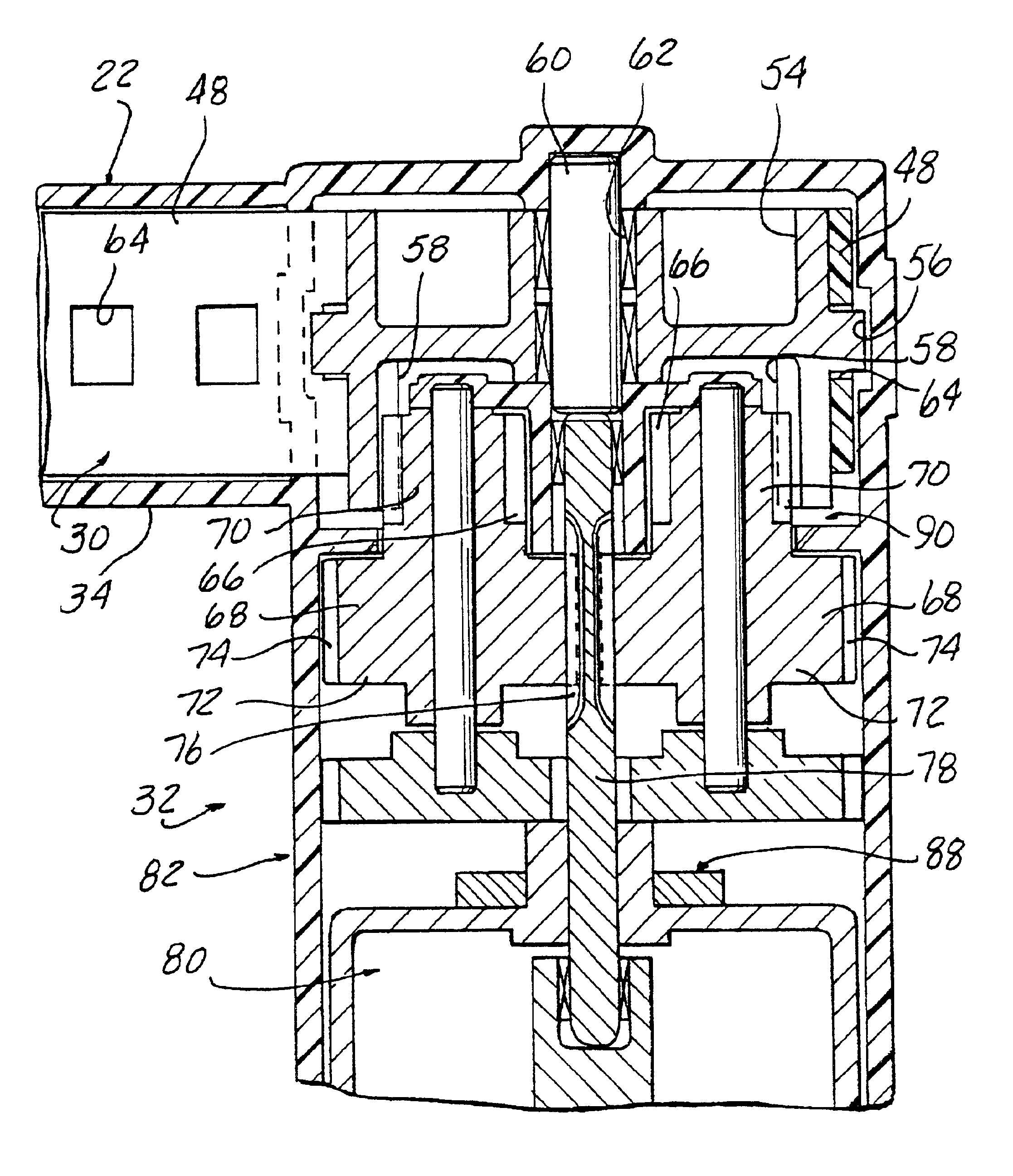
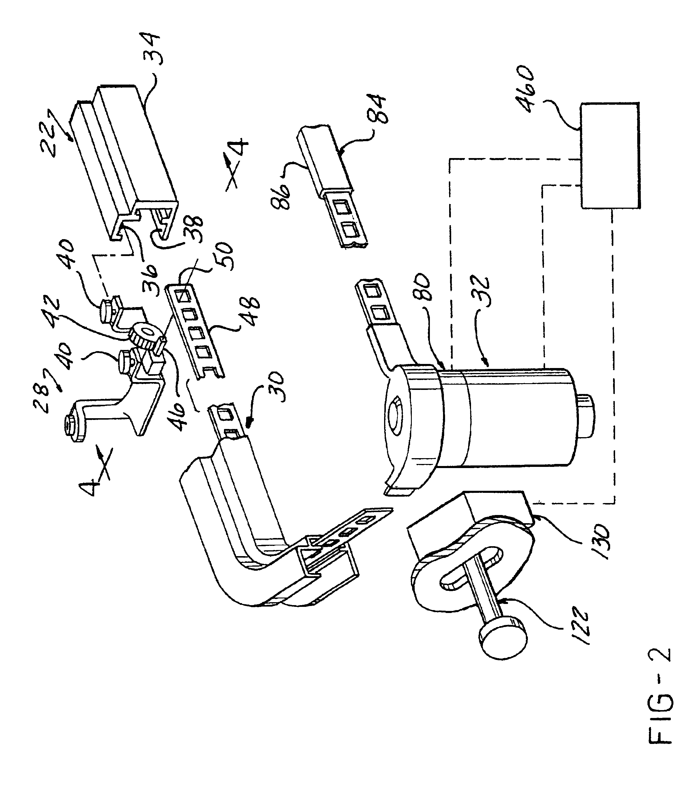
[0009]The present invention provides for automatically closing sliding doors such that the controller and motor drive translates the door along the entire fixed path during opening and closing movement to carry the fork bolt or striker on the door through the secondary latch position to the primary latch position to ensure full door security and sealing. The present invention physically pulls the door and connected striker or fork bolt into the corresponding fork bolt or striker connected to a frame defining the opening, through the secondary position and into the primary latch position, then initiates power striker motion to move the door into the weather strip seals surrounding the opening. The center rear hinge roller track is modified to accept a push / pull drive member and the translation means is coupled to the track for pushing and pulling the door open and closed. The advantage of the present invention is to pull the roller assembly and door fork bolt assembly into the power striker all the way to the primary latch position, passed the secondary position. Previously known power drive systems required high momentum to ensure proper closing of the sliding door assemblies for van-type vehicles. The power striker of the present invention then actuates a power striker to pull the door into the seals. If the translator motor has sufficient power, the latch mechanism could be fixed. The present invention provides mechanical advantage to pull the door into the primary latch position through the secondary latch position with a drive member, such as DYMETROL tape, and then uses a power striker to ensure sealing. The drive member pushes the door open during initial opening movement, which is an action that takes far less force than required to pull the door into the weather strip seals when the fork bolt and striker are in the primary latch position.

Problems solved by technology

If the striker and latch do not reach the primary latch position with respect to one another, the powered movement of the striker from its outboard position to its inboard position would not be sufficient to bring the door to the fully closed position in sealed engagement with the frame around the periphery of the door opening.

Method used


Image

  • Method for controlling a power sliding van door
  • Method for controlling a power sliding van door
  • Method for controlling a power sliding van door

Examples


Embodiment Construction

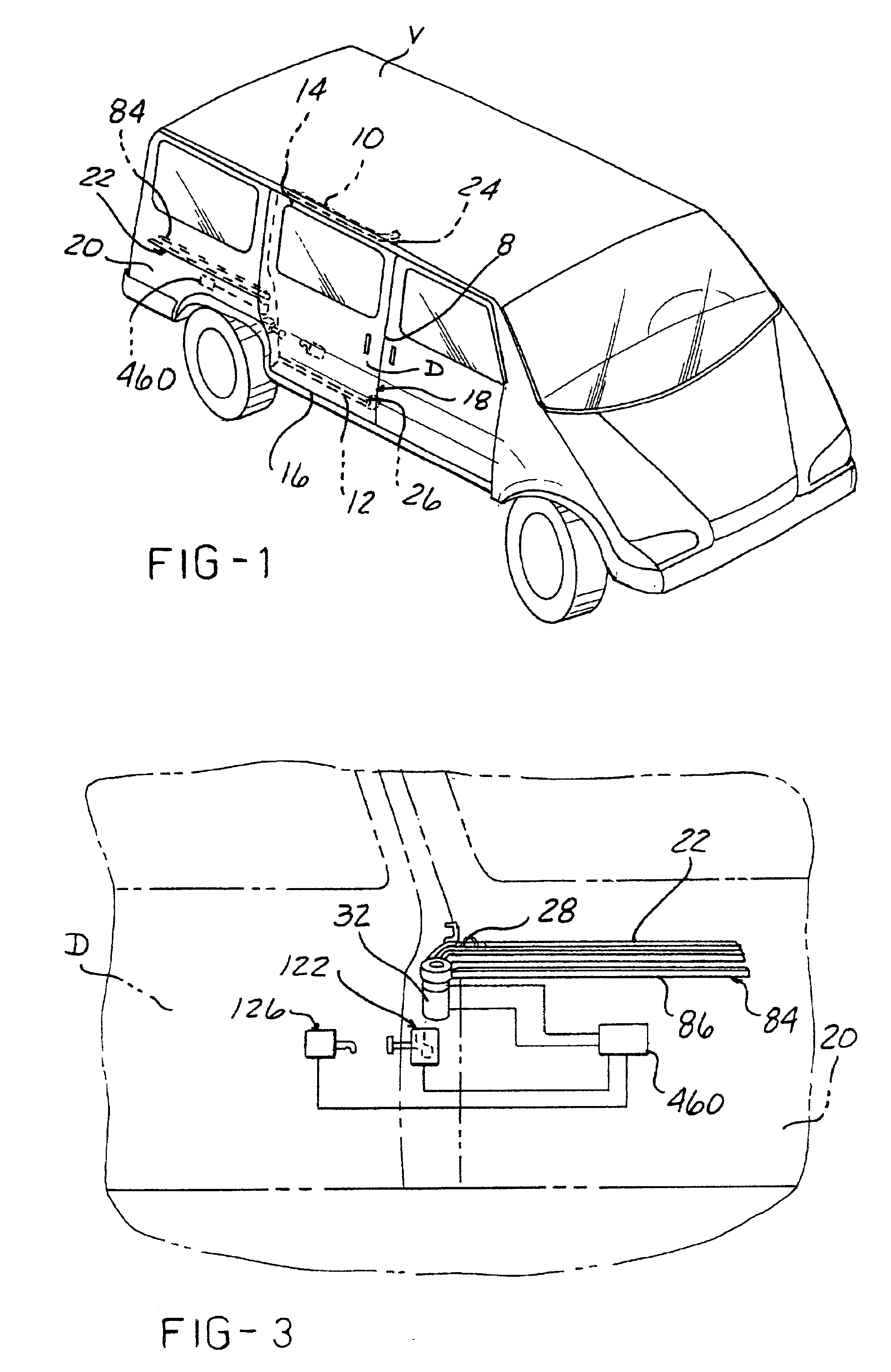
[0041]In FIGS. 1 and 3, there is shown a barrier, for example a wall of a vehicle such as a van V, having a movable closure 8, such as a sliding door D located on at least one side of the vehicle. Vans using such sliding doors have been available for years and the structural arrangements by which the door is mounted on the vehicle for manual movement between the closed position shown in FIG. 1, where the door is sealingly seated in a door opening, and an open position in which the door is disposed at the side of the van rearwardly of the door opening, is well known. In the standard arrangement, the door is latched in its closed position, typically by mechanical latches at the front and rear edges of the door, the latches being mechanically linked to a latch actuator mounted within the door to be simultaneously released by manual actuation of appropriate door handles or electronically released in response to a signal from an electronic control switch or unit. In many cases, the rear ...


PUM


Abstract

A power drive system is adapted for a sliding door mounted on at least one side of a vehicle for sliding movement forwardly and rearwardly of the vehicle. The system includes a reversible motor. A bracket is guided within a guide along a fixed path between the opened and closed positions of the door. An elongated drive member is slidably disposed within the guide and connected to the bracket at one end for driving the bracket along the fixed path. A translator mechanism operably engages with the drive member for powering movement of the door. The translator mechanism can include a rotatable hub, operably engageable with the drive member, a gear transmission for driving the hub, and a clutch mechanism for connecting the motor to the transmission. The translator mechanism preferably has sufficient power to pull the sliding door into a primary latch position with respect to the corresponding portions of a latch mechanism attached to the door and frame defining the door opening. A power striker moves the door into and out of sealing engagement with the frame. A lock mechanism selectively maintains the latch in a locked position. At least one sensor provides an input signal to a control system corresponding to movement of the door, position of the lock mechanism, and position of the power striker for controlling the door drive unit, power striker drive unit, and lock mechanism drive unit in accordance with a program stored in memory.

Description

RELATED APPLICATIONS[0001]The present application is a continuation of U.S. patent application Ser. No. 09 / 426,651 filed Oct. 25, 1999, now U.S. Pat. No. 6,430,875, which is a divisional of U.S. patent application Ser. No. 09 / 164,681 filed Oct. 1, 1998, now U.S. Pat. No. 5,979,114 issued on Nov. 9, 1999, which is a continuation-in-part of U.S. patent application Ser. No. 08 / 908,126 filed Aug. 11, 1997, now U.S. Pat. No. 5,906,071 issued May 25, 1999, which is a continuation of U.S. patent application Ser. No. 08 / 575,643 filed Dec. 20, 1995, now abandoned, which was a continuation-in-part application of U.S. patent application Ser. No. 08 / 501,557 filed Jul. 12, 1995, now U.S. Pat. No. 5,582,279 issued Dec. 10, 1996.FIELD OF THE INVENTION[0002]The present invention relates to a control system for a power drive for moving a movable closure, such as a sliding door along a fixed path between an open position and a closed position with respect to a portal defining a passage through a barr...

Claims


Application Information

Patent Timeline
IPC IPC(8): B60J5/06E05F15/14E05B65/12F16D43/16F16D43/02F16D43/24F16D43/00F16D43/18E05D15/10
CPCB60J5/06E05F15/638E05B81/22F16D43/02F16D43/16F16D43/18F16D43/24E05B81/20E05D2015/1055E05Y2201/22E05Y2201/232E05Y2201/246E05Y2201/434E05Y2600/458E05Y2800/11E05Y2800/114E05Y2900/531E05Y2400/336E05Y2400/354E05B81/21E05Y2400/3016E05Y2400/3013
Inventor CLARK, MARIAN E.BUCHANAN, JR., HARRY CHARLESJACKSON, JR., JAMES A.
Owner VALEO ELECTRICAL SYST
Learn More