
Methods and apparatus for providing power to electronic circuitry

Inactive Publication Date: 2005-06-07
EMC IP HLDG CO LLC
View PDF5 Cites 23 Cited by
  • Summary
  • Abstract
  • Description
  • Claims
  • Application Information

AI Technical Summary

Benefits of technology

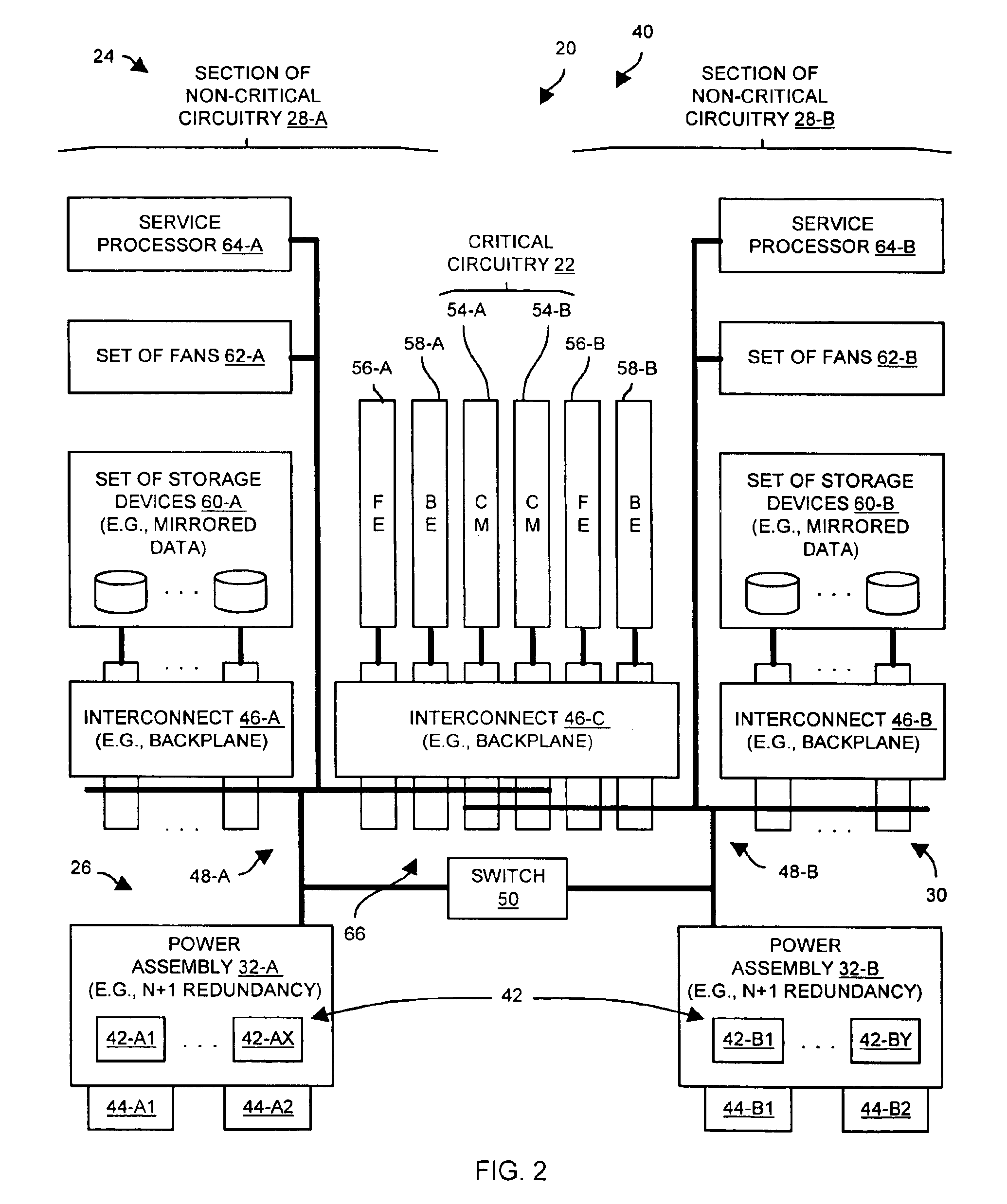
[0006]In contrast to the above-identified conventional approaches to powering a computer system which simply uses N+1 redundancy, an embodiment of the invention is directed to techniques for powering an electronic system that can distinguish between critical and non-critical circuitry within the system. A first power assembly and a second power assembly provide power to the critical and non-critical circuitry such that a failure of one power assembly results in the remaining power assembly continuing to power the critical circuitry and a portion of the non-critical circuitry in order to continue operation. Each power assembly can include one or more redundant power supplies (e.g., each power assembly having N+1 redundancy) so that, even if an entire power assembly fails and one or more power supplies in the remaining power assembly fails (i.e., even if the system encounters multiple power supply failures), the electronic system can remain operational.

Problems solved by technology

Unfortunately, there are deficiencies to the above-identified conventional approach to powering a computer system which simply uses N+1 redundancy.
For example, the data storage system cannot remain operational indefinitely when more than one power supply fails.
When this occurs, the hosts can no longer store and retrieve data using the data storage system.
A first power assembly and a second power assembly provide power to the critical and non-critical circuitry such that a failure of one power assembly results in the remaining power assembly continuing to power the critical circuitry and a portion of the non-critical circuitry in order to continue operation.
The set of connections is configured to connect the first and second power assemblies to the critical circuitry and the non-critical circuitry such that, when the first and second power assemblies operate to power the critical and non-critical circuitry through the set of connections, (i) a failure of only the second power assembly results in the first power assembly continuing to power the critical circuitry and the first section of the non-critical circuitry, and (ii) a failure of only the first power assembly results in the second power assembly continuing to power the critical circuitry and the second section of the non-critical circuitry.
Accordingly, a failure of one of the power assemblies still results in the remaining power assembly providing power to the cache memory in order to avoid losing data in the cache memory.

Method used


Image

  • Methods and apparatus for providing power to electronic circuitry
  • Methods and apparatus for providing power to electronic circuitry
  • Methods and apparatus for providing power to electronic circuitry

Examples


Embodiment Construction

[0025]An embodiment of the invention is directed to techniques for powering an electronic system having critical and non-critical circuitry. A first power assembly and a second power assembly provide power to the critical and non-critical circuitry such that a failure of one power assembly results in the remaining power assembly continuing to power the critical circuitry and a portion of the non-critical circuitry in order to continue operation. Each power assembly can include one or more redundant power supplies (e.g., each power assembly having N+1 redundancy) so that, even if an entire power assembly fails and one or more power supplies in the remaining power assembly fails (i.e., even if the system encounters multiple power supply failures), the electronic system can remain operational.

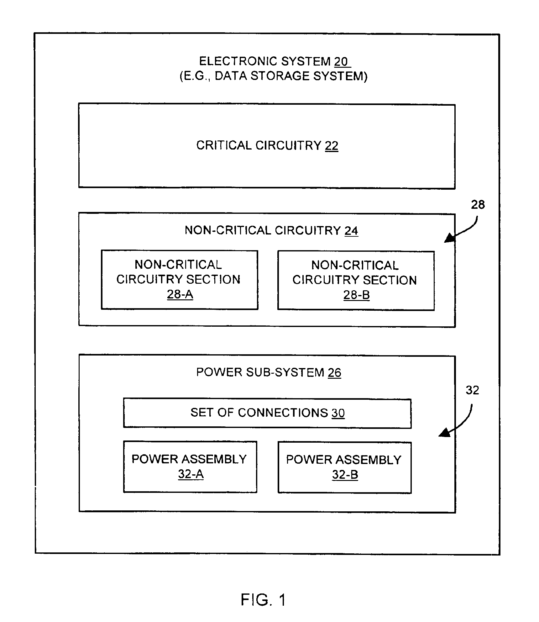
[0026]FIG. 1 shows an electronic system 20 which is suitable for use by the invention. The electronic system 20 includes critical circuitry 22, non-critical circuitry 24 and a power sub-system 26....


PUM


Abstract

An electronic system has critical circuitry, non-critical circuitry having a first section and a second section, and a power sub-system. The power sub-system has a first power assembly, a second power assembly, and a set of connections. The set of connections is configured to connect the first and second power assemblies to the critical circuitry and the non-critical circuitry such that, when the first and second power assemblies operate to power the critical and non-critical circuitry through the set of connections, (i) a failure of only the second power assembly results in the first power assembly continuing to power the critical circuitry and the first section of the non-critical circuitry, and (ii) a failure of only the first power assembly results in the second power assembly continuing to power the critical circuitry and the second section of the non-critical circuitry.

Description

BACKGROUND OF THE INVENTION[0001]A typical computer system includes, among other things, a processor, memory (volatile and non-volatile), and a power supply. The processor runs programs (e.g., an operating system, high-level applications, etc.) which are typically stored in the memory. The power supply powers circuitry within the processor and the memory.[0002]Some computer systems are configured to perform specialized operations. For example, a typical data storage system is a specialized computer system which is configured to perform load and store operations on behalf of one or more external hosts. Such a data storage system can include additional or enhanced computer components for performing the load and storage operations. In particular, some of the volatile memory of a data storage system is typically configured to operate as an input / output (I / O) cache (i.e., cache memory) for temporarily buffering data exchanged between the external hosts and the non-volatile memory (e.g., ...

Claims


Application Information

Patent Timeline
IPC IPC(8): G06F11/00
CPCG06F11/2015
Inventor MACARTHUR, ROBERTGALLAGHER, BRIANPIGNOLET, LAWRENCE
Owner EMC IP HLDG CO LLC
Learn More