Perpendicular magnetic recording head including nonmagnetic layer overlaying main pole layer
a technology of magnetic recording head and main pole layer, which is applied in the direction of magnetic recording head, data recording, instruments, etc., can solve the problems of reducing the height, affecting the control of the end face area b>5/b>a /i>a /i> within a predetermined range, and reducing the recording characteristics such as overwriting characteristics, so as to achieve simplified control of the etching process
- Summary
- Abstract
- Description
- Claims
- Application Information
AI Technical Summary
Benefits of technology
Problems solved by technology
Method used
Image
Examples
first embodiment
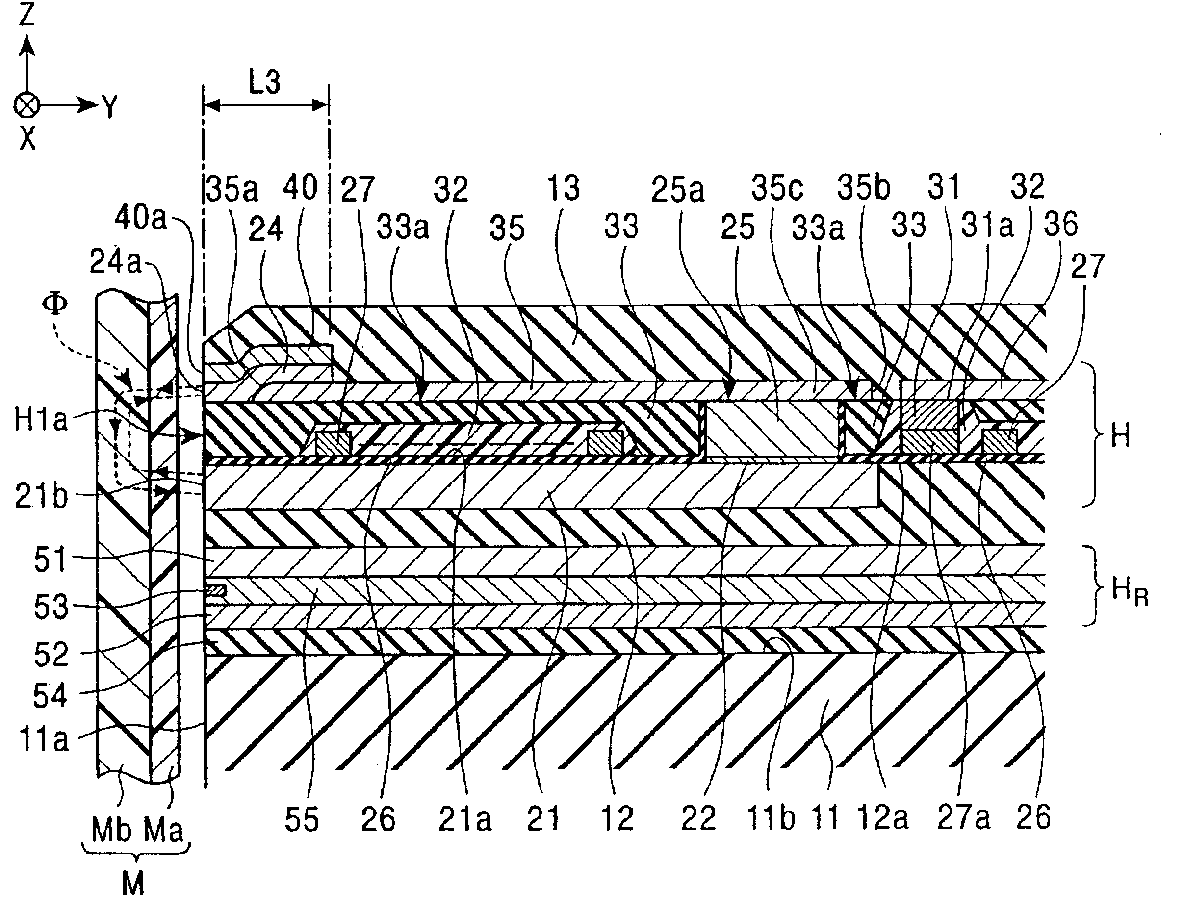
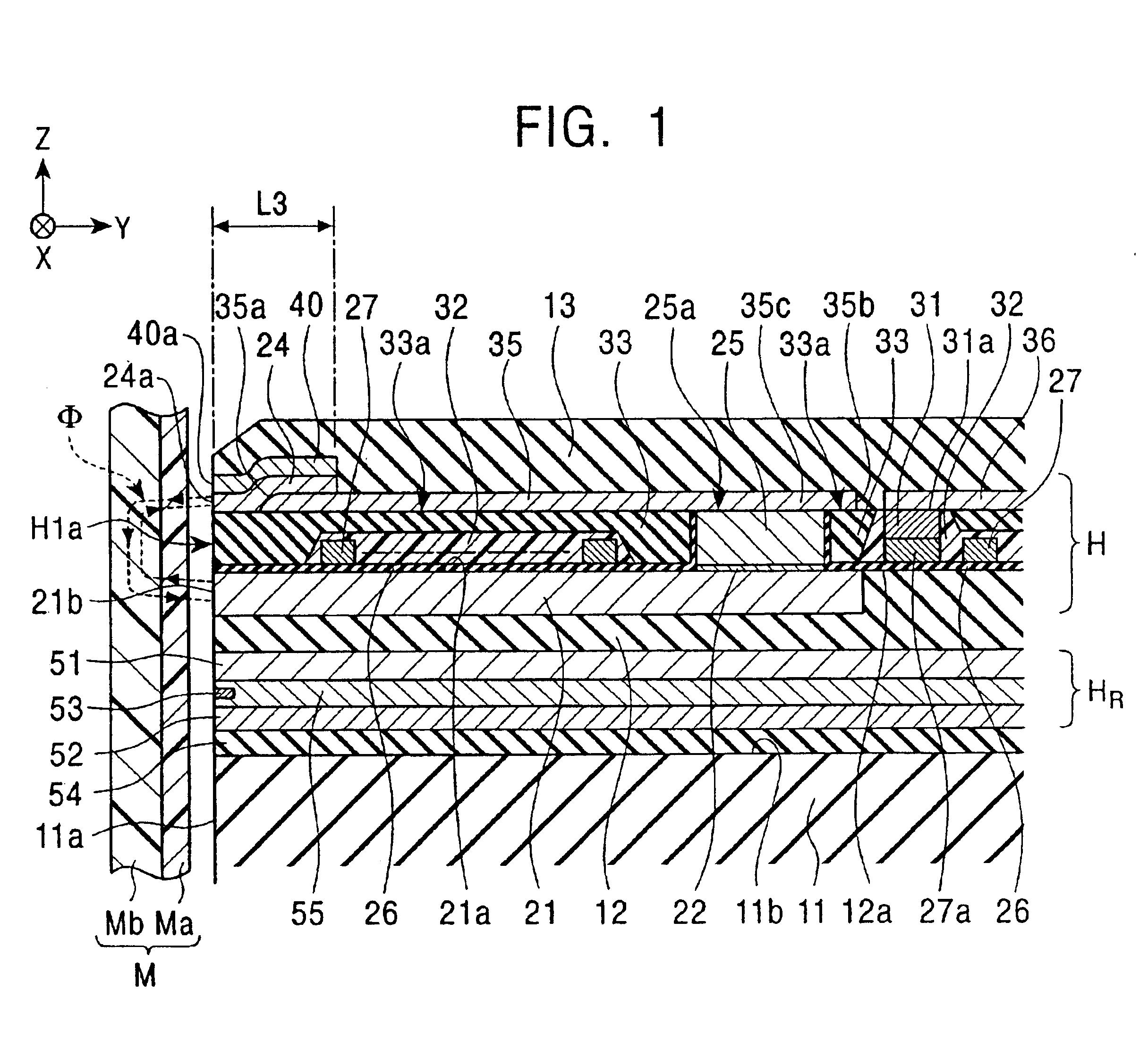
[0083]FIG. 1 is a vertical cross-sectional view showing the structure of a magnetic head comprising a perpendicular magnetic recording head according to the present invention.
[0084]A perpendicular magnetic recording head H shown in FIG. 1 applies a perpendicular magnetic field to a recording medium M to magnetize a hard layer Ma of the recording medium M in a perpendicular direction.
[0085]The recording medium M is disk shaped. A hard layer Ma exhibiting high residual magnetization is provided on the surface of the recording medium M, and a soft layer Mb exhibiting high permeability is provided under the hard layer Ma. The recording medium M is rotated around the center of the disk.
[0086]A slider 11 of the perpendicular magnetic recording head H is composed of a ceramic material such as Al2O3.TiC. An opposing face 11a of the slider 11 opposes the recording medium M. The slider 11 is lifted from the surface of the recording medium M and slides over the recording medium M by an airflow...
second embodiment
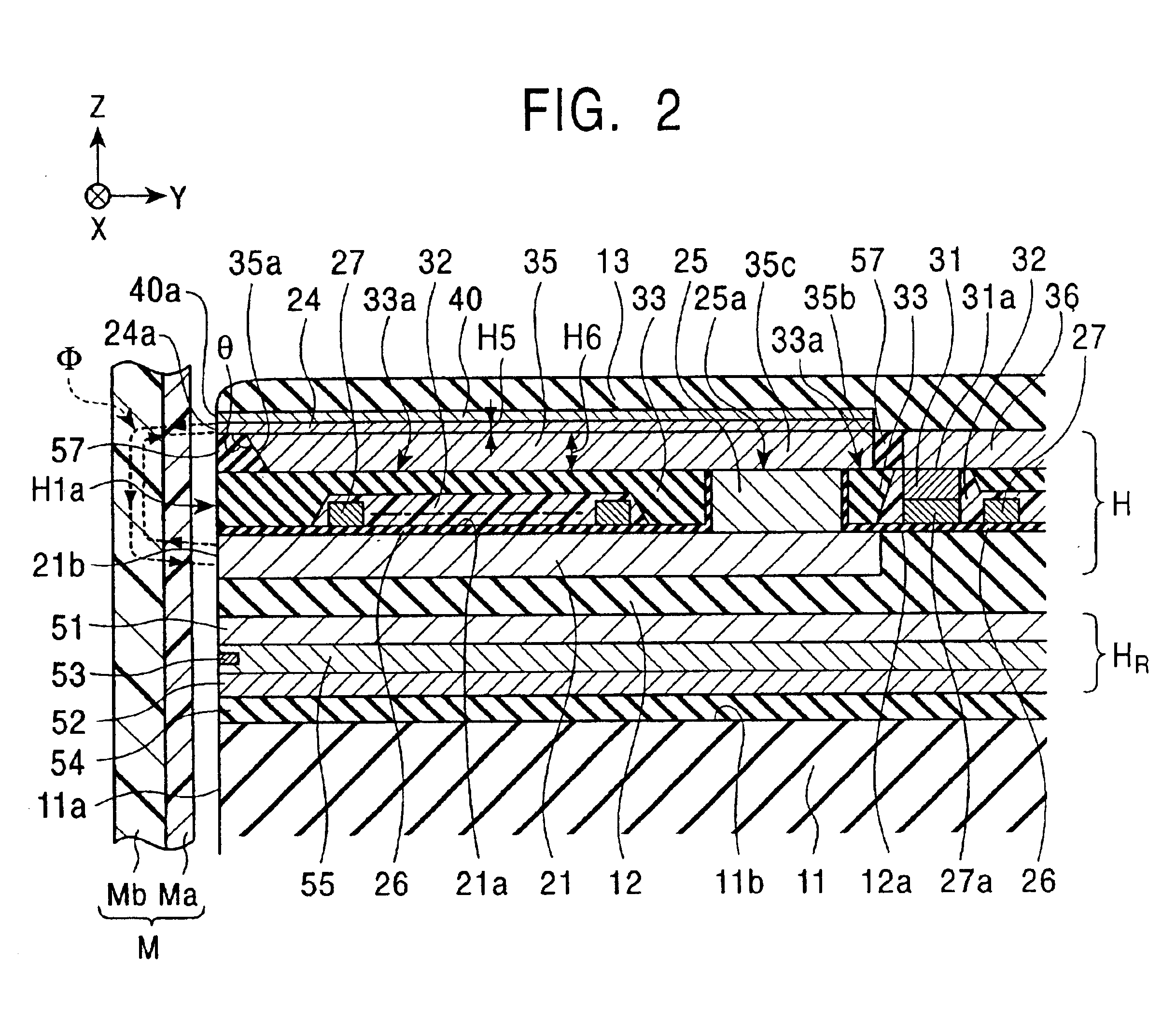
[0102]FIG. 2 is a vertical cross-sectional view of a magnetic head incorporating a perpendicular magnetic recording head according to the present invention.
[0103]This perpendicular magnetic recording head differs from that shown in FIG. 1 particularly in the structure of the yoke layer 35. In FIG. 2, the yoke layer 35 is formed on the top face 33a of the insulating layer 33, and the rear portion 35c of the yoke layer 35 is formed on the top face 25a of the connection layer 25. The rear portion 35c and the connection layer 25 are magnetically connected.
[0104]As shown in FIG. 2, the front end face 35a of the yoke layer 35 is disposed at some distance inward in the height direction (the Y direction in the drawing) from the opposing face H1a and is not exposed at the opposing face H1a.
[0105]The front end face 35a is formed into a flat face or a curved face tilting from the top left to the bottom right in the drawing. The external angle θ defined by the front end face 35a and the top fa...
third embodiment
[0112]FIG. 3 is a vertical cross-sectional view of a magnetic head incorporating a perpendicular magnetic recording head according to the present invention.
[0113]In FIG. 3, unlike in FIGS. 1 and 2, the main pole layer 24 is formed on the planarized insulating layer 33 and the nonmagnetic layer 40 is formed overlaying the main pole layer 24. The yoke layer 35 in this embodiment is integrated into the main pole layer 24 and the rear portion of the main pole layer 24 functions as the yoke layer 35. The yoke layer 35 and the connection layer 25 are magnetically connected.
[0114]The shapes of the front ends 24a and 40a of the main pole layer 24 and the nonmagnetic layer 40, respectively, according to the present invention will now be described. FIGS. 4 and 5 are partial front views of the perpendicular magnetic recording heads shown in FIGS. 1 to 3.
[0115]As shown in FIGS. 4 and 5, a plating base layer 71 is formed between the main pole layer 24 and either the insulating layer 33 or the se...
PUM
| Property | Measurement | Unit |
|---|---|---|
| external angle | aaaaa | aaaaa |
| angle | aaaaa | aaaaa |
| angle | aaaaa | aaaaa |
Abstract
Description
Claims
Application Information
 - R&D
- Intellectual Property
- Life Sciences
- Materials
- Tech Scout
- Unparalleled Data Quality
- Higher Quality Content
- 60% Fewer Hallucinations
Browse by: Latest US Patents, China's latest patents, Technical Efficacy Thesaurus, Application Domain, Technology Topic, Popular Technical Reports.
© 2025 PatSnap. All rights reserved.Legal|Privacy policy|Modern Slavery Act Transparency Statement|Sitemap|About US| Contact US: help@patsnap.com


