
Tape drive servo operation by use of servo pattern width measurements

a servo pattern and tape drive technology, applied in the field of linear data storage devices with servo controlled head positioning, can solve the problems of data track placement error and errors in accurately locating data tracks on tape, and achieve the effect of improving servo system and more accurate tape servo pattern following

Inactive Publication Date: 2005-06-07
IBM CORP
View PDF8 Cites 18 Cited by
  • Summary
  • Abstract
  • Description
  • Claims
  • Application Information

AI Technical Summary

Benefits of technology

[0007]It is an object of the present invention, to provide an enhanced servo system for linear data storage devices. The present invention provides more accurate tape servo pattern following by measuring the width of the center band of the servo pattern written on the magnetic tape. The measured width is used to produce a corrected position error signal that provides improved servo track following to maintain the tape head at an optimal alignment for writing and reading data tracks on the tape.
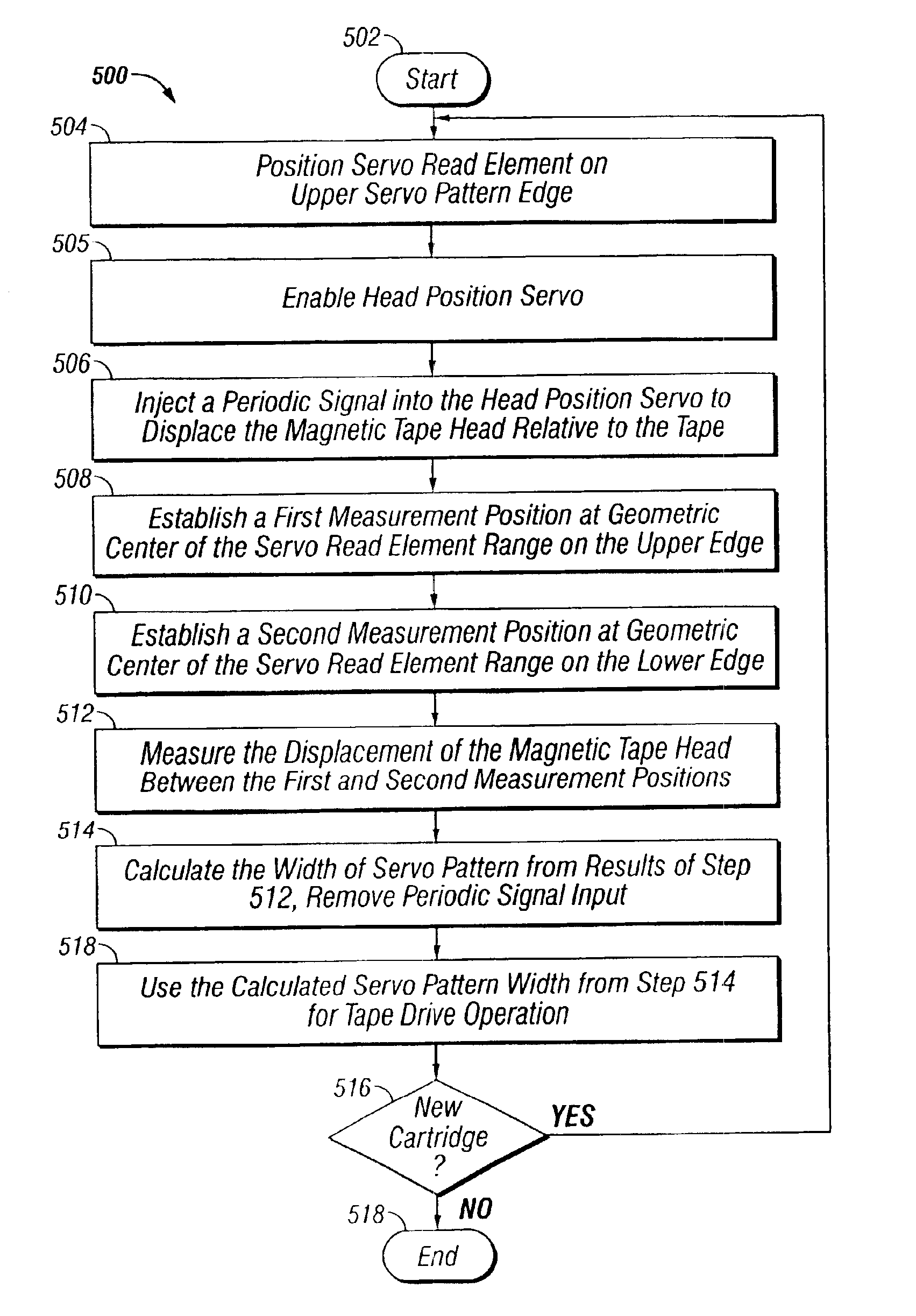
[0009]In a first embodiment the width of the servo pattern written on the magnetic tape is measured each time a cartridge containing the magnetic tape is inserted into the tape drive. The head position servo is enabled while the servo read element is positioned at the upper edge of the servo pattern. A periodic signal is then injected into the head position servo to move the head relative to the servo pattern edge. The PES response for the servo read element on the upper edge and a first measurement position corresponding to the upper edge are obtained. The servo read element is then moved to the lower edge. The PES response for the servo read element on the lower edge and a second measurement position corresponding to the lower edge are obtained. The periodic signal is then adjusted to move the magnetic head so that the servo read element moves between the first and second measurement positions. The periodic signal is further adjusted to reduce any errors resulting from magnetic tape motion relative to the magnetic tape head containing the servo read element. Multiple measurements of the servo pattern width are obtained as this periodic signal drives the magnetic head to move between the upper and lower edges, and then processed to obtain an accurate measurement of the servo pattern width. The resulting servo pattern width is used to provide a calibrated offset for the head position servo which compensates for any deviation of the written width of the center band of the servo pattern. The actual width of the servo pattern is measured each time the tape is introduced into a drive as part of an initialization process resulting in improved head position servo performance.
[0011]Another object of the present invention is to provide an improved servo control head positioning system for linear data storage devices using measurements taken from the linear medium to more accurately position the head-to-track alignment.

Problems solved by technology

Variations in the servo patterns may result in a data track placement error.
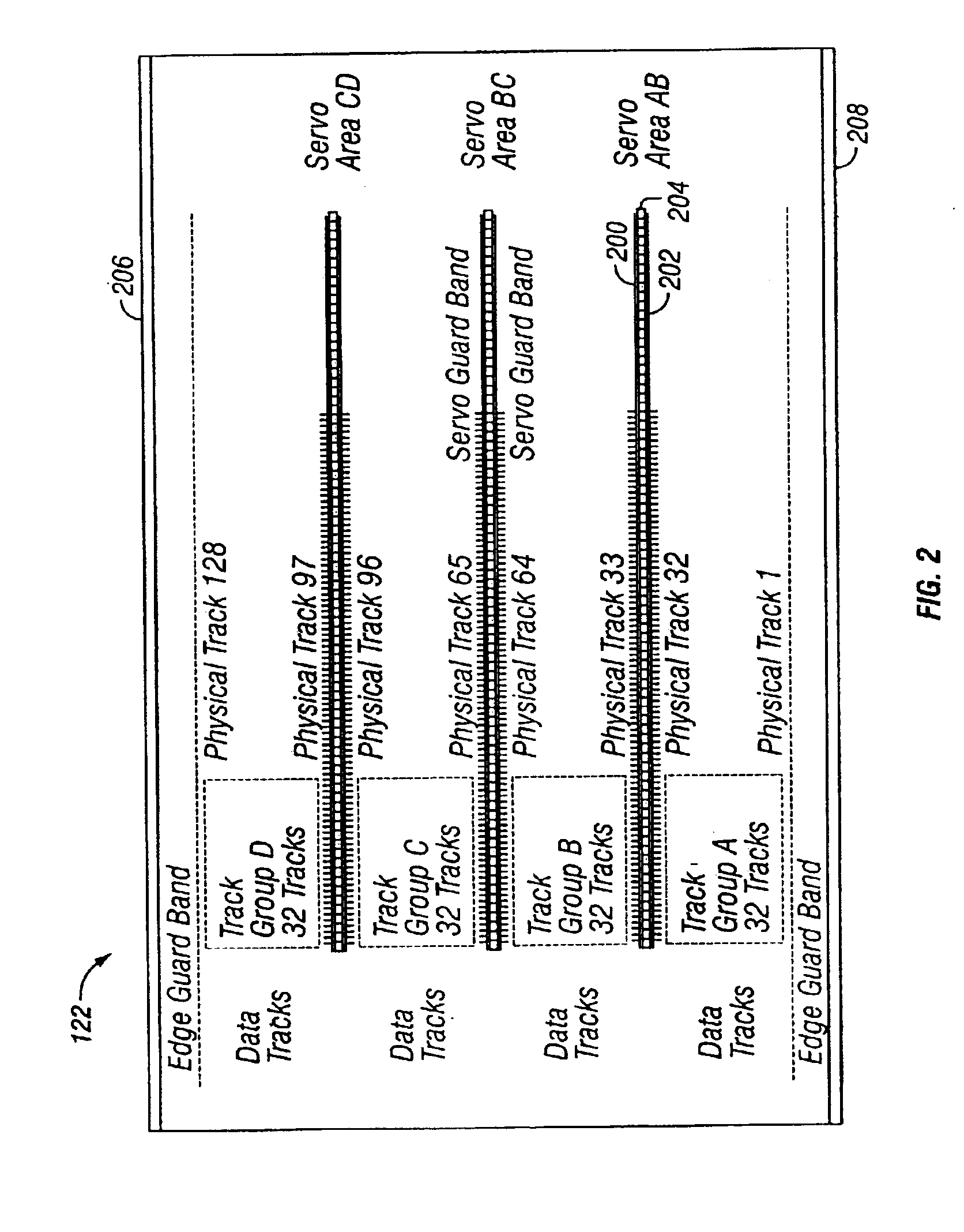
In practice, there is variation in the servo pattern so that this assumption can cause errors in accurately locating the data tracks on the tape.

Method used


Image

  • Tape drive servo operation by use of servo pattern width measurements
  • Tape drive servo operation by use of servo pattern width measurements
  • Tape drive servo operation by use of servo pattern width measurements

Examples


Embodiment Construction

[0021]One aspect of the present invention concerns a tape storage system such as that shown in the U.S. Pat. No. 5,946,159 issued on Aug. 31, 1999 and entitled, “Servo Edge Correction Using Edge Samples Taken by Independently Positioned Servo Elements” in the names of Alex Chliwnyj, et al and assigned to the assignee of the present invention. The entirety of the '159 patent is incorporated herein by reference. The present invention is an improvement to the '159 patent.

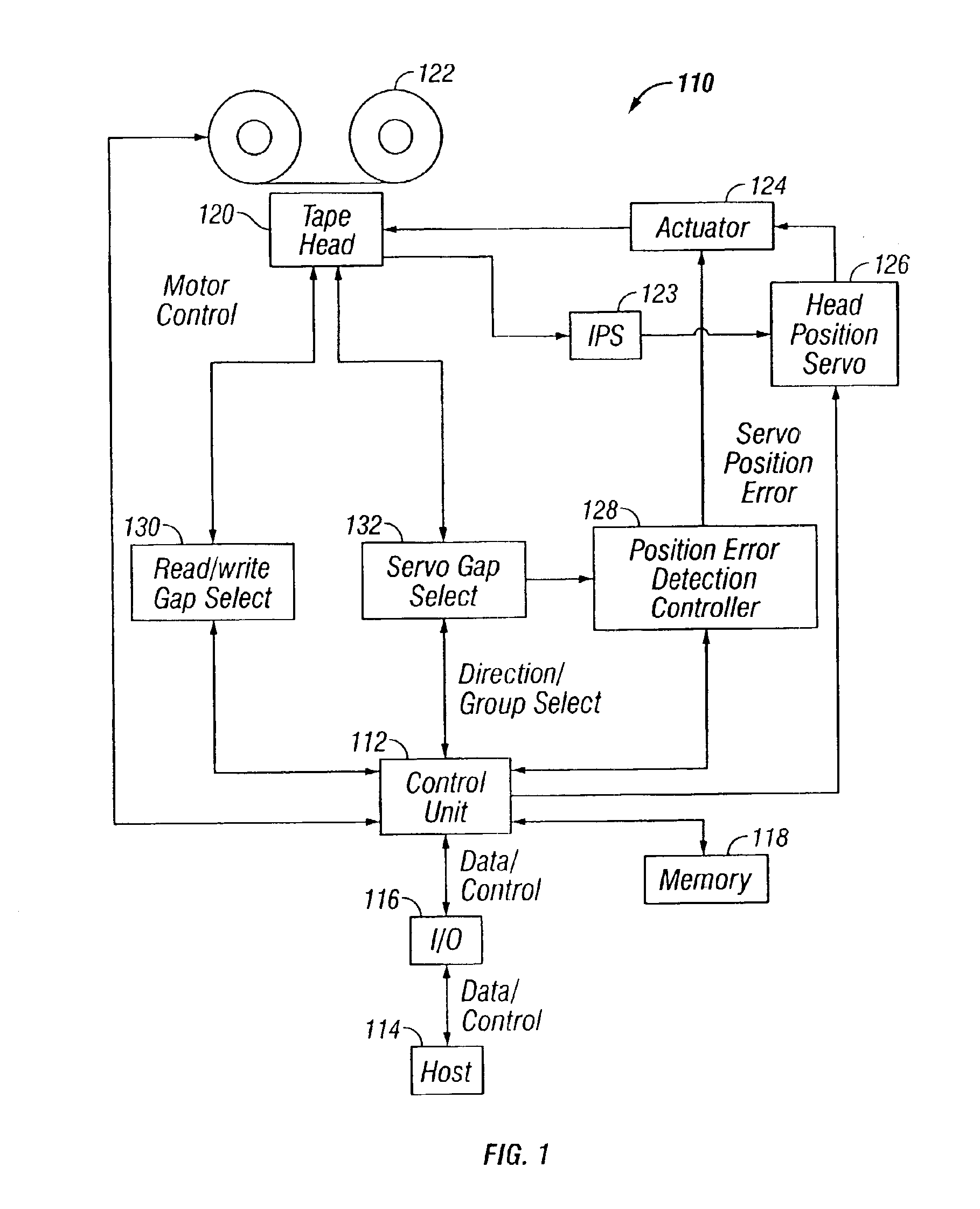
[0022]In FIG. 1, a tape storage system 110 includes hardware components and interconnections used in the present invention. Broadly, the system 110 operates to read and write data from and to a magnetic tape 122 that contains servo information for transversely guiding a tape head 120. Herein, the term magnetic tape head and tape head are used interchangeably to describe the magnetic tape head used with a magnetic tape in a tape drive. In the preferred embodiment, the system 110 includes features of the tape system of U...


PUM

PropertyMeasurementUnit
frequencyaaaaaaaaaa
frequencyaaaaaaaaaa
widthaaaaaaaaaa

Abstract

A system, method and an article of manufacture to provide more accurate magnetic tape servo operation are disclosed. Accurate measurements of the width of the servo pattern written on the magnetic tape are accomplished in the presence of relatively large motion of the magnetic tape. The accurate measurements of the width of the servo pattern are used to produce a corrected position error signal that provides improved servo track following to maintain the tape head at an optimal alignment for writing and reading data tracks on the tape.

Description

TECHNICAL FIELD[0001]The present invention relates generally to linear data storage devices with servo controlled head positioning. More particularly, the invention provides improved servo operation in a magnetic tape data storage device by providing a corrected position error signal for accurate track following.BACKGROUND OF THE INVENTION[0002]A data storage medium will often contain various servo signals to precisely position the read / write heads with respect to the tracks of data stored on the medium. Magnetic tape systems, such as the IBM 3590, use servo patterns on the data storage medium to generate the servo signals used to position the read / write heads. In the IBM 3590 tape cartridges, the servo pattern is often pre-written on data storage medium (magnetic tape) contained in the cartridge. The servo pattern for the IBM 3590 includes three pairs of servo edges, each edge being a boundary between the adjacent contrasting servo signals written on the tape. Nominally, the physic...

Claims


Application Information

Patent Timeline
Patent Type & Authority Patents(United States)
IPC IPC(8): G11B5/584G11B27/36
CPCG11B27/36G11B5/584
Inventor CHLIWNYJ, ALEXSWANSON, DAVID LEE
Owner IBM CORP
Learn More