USB connector

Inactive Publication Date: 2005-06-07
YAZAKI CORP
View PDF6 Cites 228 Cited by
  • Summary
  • Abstract
  • Description
  • Claims
  • Application Information

AI Technical Summary

Benefits of technology

[0014]It is therefore an object of the present invention to provide a USB connector, which restrains a plug and a jack from being loosely latched together in order to prevent the plug from slipping off the jack even when vibration or external force is applied thereto and easily releases the latching of the plug as the need arises, so that an excellent fitting property is provided.
[0022]In the above configuration, the shield case is slidably fitted into the shield shell when the plug is inserted into the jack and the jack terminals and the plug terminals electrically contact and moreover a computer body and the peripheral equipment are connected with the contact portion shielded. As the shield case is provided with the latching portions and as the shield shell is provided with mating portions, the latching portions and the mating portions are engaged together so that the jack and the plug are latched together without looseness, whereby the plug is prevented from slipping off the jack because of vibration or external force inadvertently applied thereto. Therefore, the latching is certainly by far improved.
[0025]In the above configuration, since latching portion is the deformable piece having the claw at the front end, the claws mate with the mating portions to ensure the latching of the plug when the plug is inserted into the jack. The latching portions are provided in the one wall portion and as no lock pieces are provided in the opposed walls of the shield shell like the related example, the outer wall face of the shield case is guided and supported by the inner wall face of the shield shell when the plug is inserted into the jack, whereby the plug stably mates with the jack without prying open the jack. As the pair of latching portions are provided, further, the lateral balance is improved and the insertion is smoothly carried out with the effect of ensuring the latching further. Therefore, the effect of ensuring the latching further is achievable and the plug is smoothly fitted into the jack, so that an excellent fitting property is provided.
[0031]In the above configuration, the projection is brought into contact with the deformable pieces by pushing the push member when the plug is pulled out of the jack and the deformable pieces are bent in the direction in which the latching is released with the claws slipped off the grooves, whereby the plug is easily removed from the jack. Therefore, the plug is easily removed from the jack and this improves the property of releasing the latching.
[0033]In the above configuration, the provision of the projections in the wall portion of the housing prevents the push member from being inadvertently pressed because of interference with the outside, so that the plug is prevented from slipping off the jack. Therefore, the latching reliability is secured even when the push member as a latch-releasing member is provided.

Problems solved by technology

The existence of different interfaces as described above makes it difficult to set computer bodies compatible with any peripheral equipment or integrate the computer body with the peripheral equipment; the problem is that there develops inconvenience in handling computers and peripheral equipment, thus increasing the manufacturing cost.
However, the related USB connector involves the following problems.

Method used


Image

  • USB connector
  • USB connector
  • USB connector

Examples


Embodiment Construction

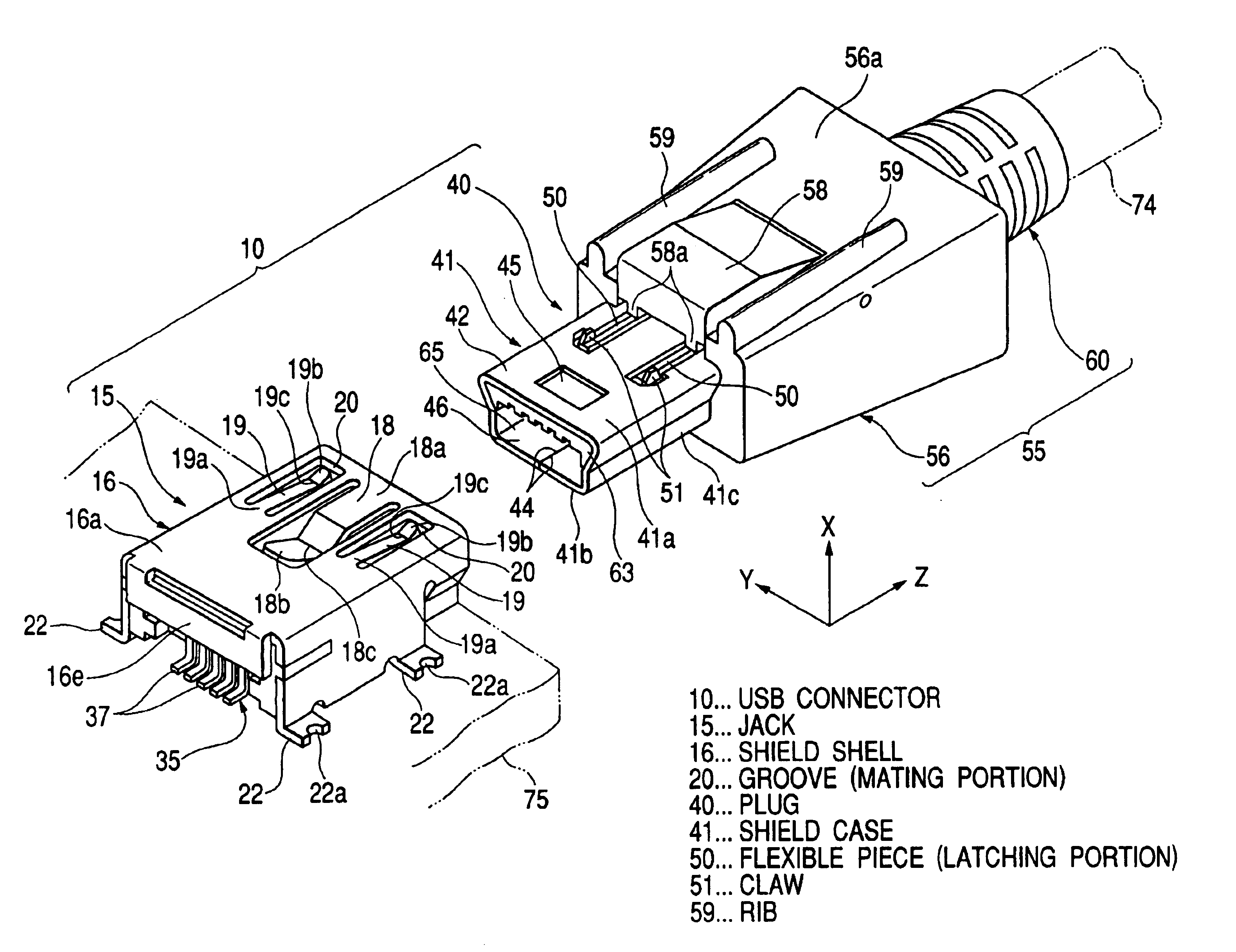
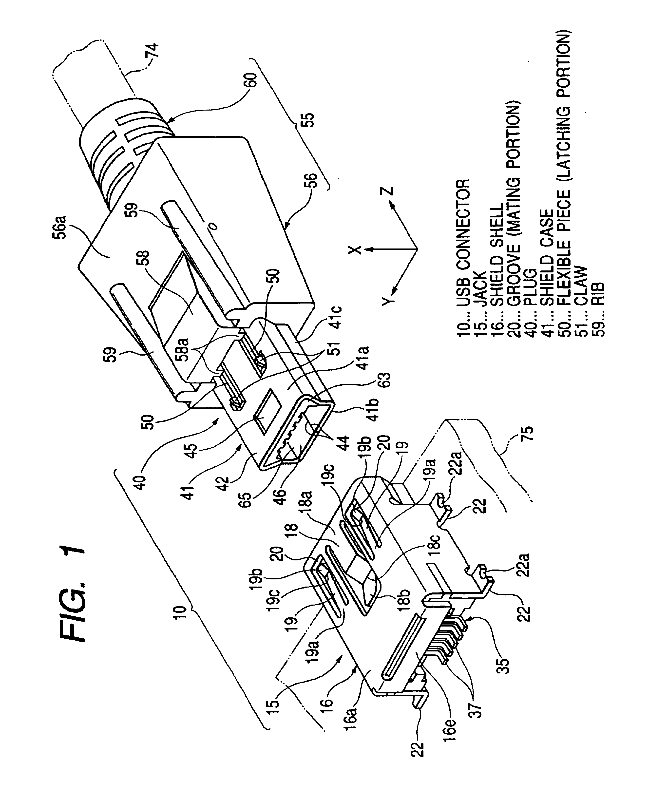
[0040]A detailed description will now be given of a preferred embodiment of the invention by reference to the drawings. FIGS. 1 to 4 show a USB connector of a embodiment according to the invention.

[0041]A USB connector 10 of FIG. 1 is a cable connector conforming to the USB interface standard and mainly used for connecting a computer body (not shown) and peripheral equipment (not shown).

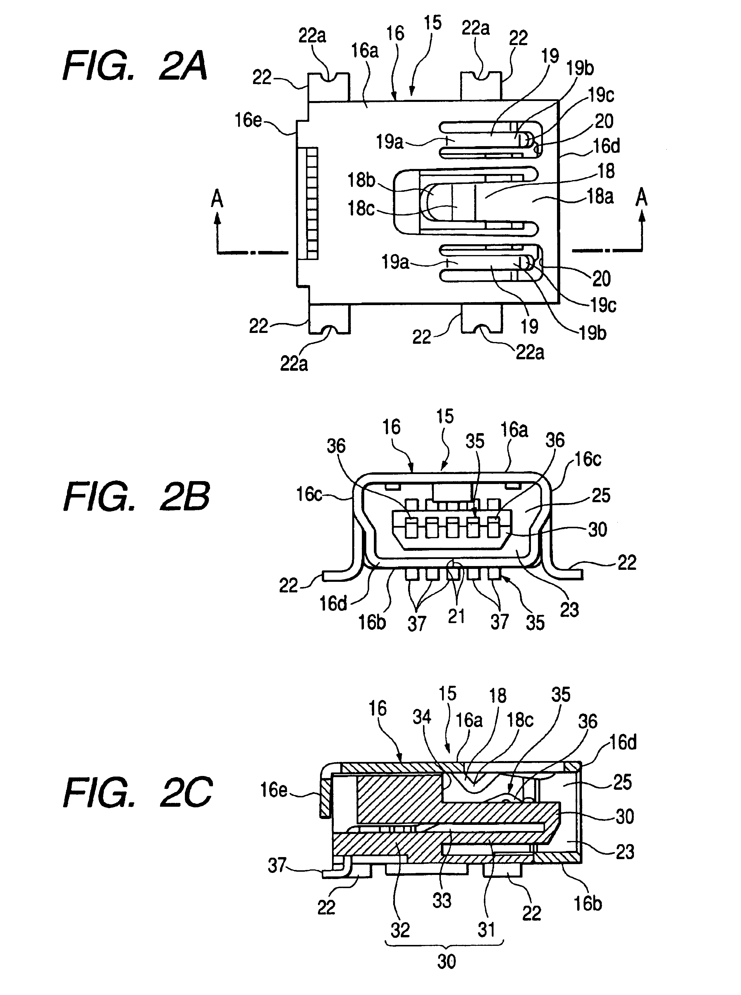
[0042]A USB connector 10 has a jack 15 fixed to a circuit board 75 such as a printed circuit board and a printed wiring board and a plug 40 provided on the peripheral equipment (not shown) side and used for setting up an electrical connection by mating with the jack 15. The jack 15 is fixed to the circuit board 75 by means of a fastening member or solder and the plug 40 is connected to the terminal portion of an electrical wire 74 drawn from the peripheral equipment. The jack 15 and the plug 40 of the USB connector 10 connected together will successively be described hereafter.

[0043]The jack 15 is a ...


PUM


Abstract

A USB connector includes a jack and a plug. The jack includes a shield shell, having jack terminals therein. The plug includes a shield case, having plug terminals to be electrically connected to the jack terminals, and fitted into the shield shell. The shield shell has a mating portion The shield case has a latching portion which engages with the mating portion when the plug is inserted into the jack.

Description

BACKGROUND OF THE INVENTION[0001]The present invention relates to a USB connector having a lock mechanism and used for electrically connecting the body of a computer such as a personal computer or a workstation and peripheral equipment including a mouse, a keyboard and so on.[0002]Recently, a mouse, a keyboard, a printer, a scanner, a modem, an external memory and the like as peripheral equipment are connected to one computer body via different interfaces. For example, a mouse and a keyboard are connected to different serial interfaces for making serial transfer; a printer and a scanner to different parallel interfaces for making parallel transfer; a modem to an RS-232C for making serial transfer; and an external memory to an SCSI interface for making parallel transfer. Moreover, an interface with the same item of peripheral equipment may vary with the computer or equipment manufacturer.[0003]The existence of different interfaces as described above makes it difficult to set computer...

Claims


Application Information

Patent Timeline
IPC IPC(8): H01R13/627H01R13/658H01R13/652H01R13/639H01R13/6582H01R24/62
CPCH01R13/6275H01R24/62H01R13/65802H01R13/6582
Inventor MORIKAWA, TAISHINARUI, FUMIOIKEMOTO, SHINICHI
Owner YAZAKI CORP
Why Eureka
Try Eureka