Temperature-controlled fuel valve, especially for a fuel-operated heating burner of a vehicle heating system

Inactive Publication Date: 2005-06-07
J EBERSPAECHER GMBH & CO KG
View PDF18 Cites 6 Cited by
  • Summary
  • Abstract
  • Description
  • Claims
  • Application Information

AI Technical Summary

Benefits of technology

[0004]The object of the present invention is to provide measures with which undesired emissions can be reduced and the quality of the combustion in a heating burner can be improved.
[0008]To make it possible to bring about the temperature-controlled switchover between different flow paths in a simple manner in the fuel valve according to the present invention, it is proposed that a first flow path area, which can be brought into connection with a feed area and which leads to a first drain area and to a second flow path area, be provided in a valve body, wherein the second flow path area leads to a second drain area. Furthermore, provisions may be preferably made for the valve member to close the first flow path area at a temperature in the first temperature range, to close the second flow path area at a temperature in the third temperature range, and not to close the first and second flow path areas at a temperature in the second temperature range.
[0011]The conversion of a change in the volume of the temperature sensor medium into a pressing movement for the valve member may be achieved, e.g., in a very simple manner by the transmission arrangement comprising a closing element that can be deformed by the change in the volume of the temperature sensor medium and a plunger that can be displaced by a deformation of the closing element.
[0013]By integrating the fuel valve according to the present invention in the area between the metering pump and the heating burner, preferably as close to the heating burner as possible, it is ensured that the line path that cannot be closed any longer is kept as short as possible. The amount of the fuel that is not burned any more when the combustion is stopped and then tends to evaporate because of the still comparatively high temperatures can be markedly reduced in this manner.

Problems solved by technology

The problem arises during the operation of such systems that fuel is still present in the line section between the metering pump and the combustion chamber on switching off, and this fuel still evaporates at least in the area of the pressure pipe close to the combustion chamber with the ignition stopped and thus leads to emissions that are potentially hazardous as to ones health.
A generally asymmetric feed of the fuel into the combustion chamber during the operation leads to a combustion that is not distributed uniformly over the combustion chamber, as a consequence of which the combustion does not take place in the optimal lambda range in all areas of the combustion chamber, which may lead to the formation of deposits.

Method used


Image

  • Temperature-controlled fuel valve, especially for a fuel-operated heating burner of a vehicle heating system
  • Temperature-controlled fuel valve, especially for a fuel-operated heating burner of a vehicle heating system
  • Temperature-controlled fuel valve, especially for a fuel-operated heating burner of a vehicle heating system

Examples


Embodiment Construction

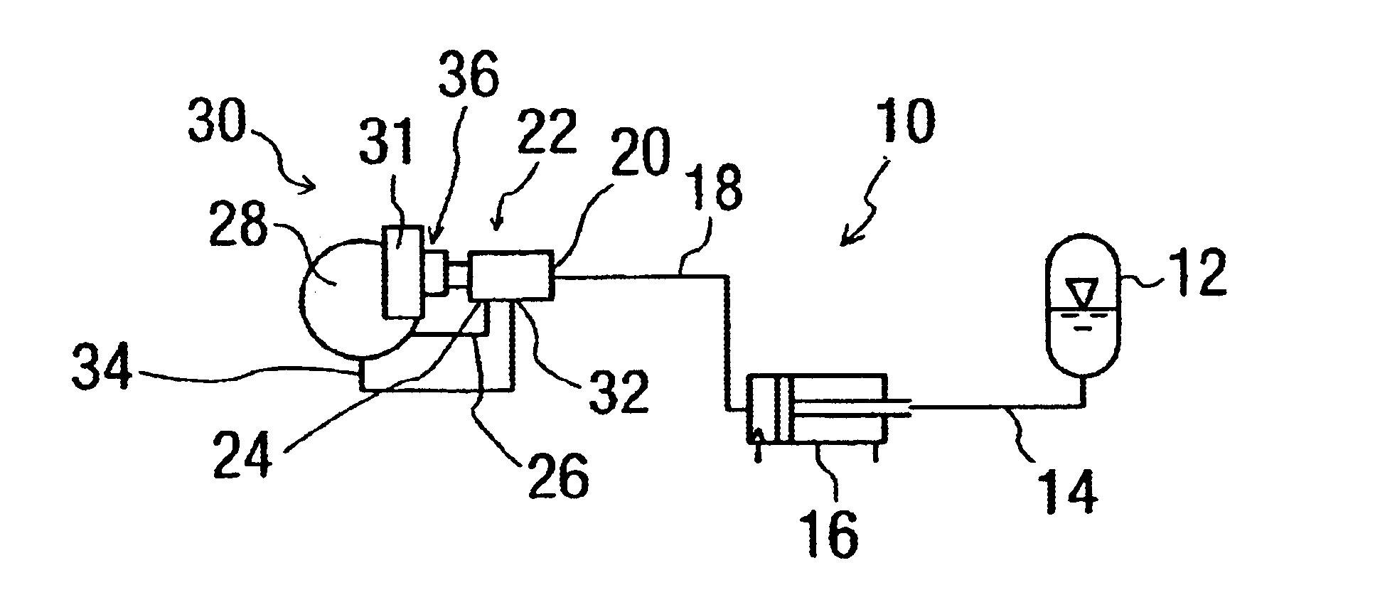
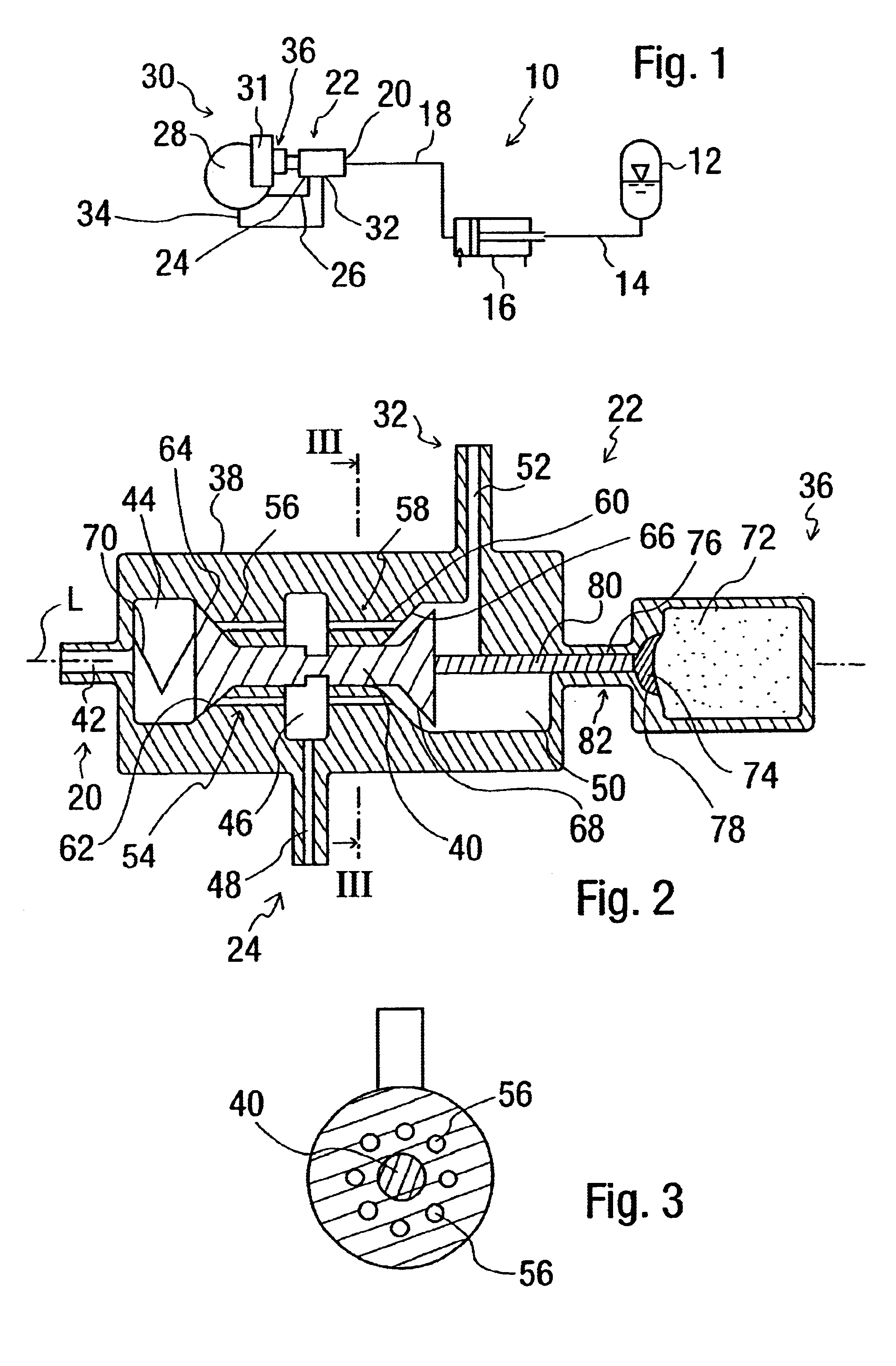
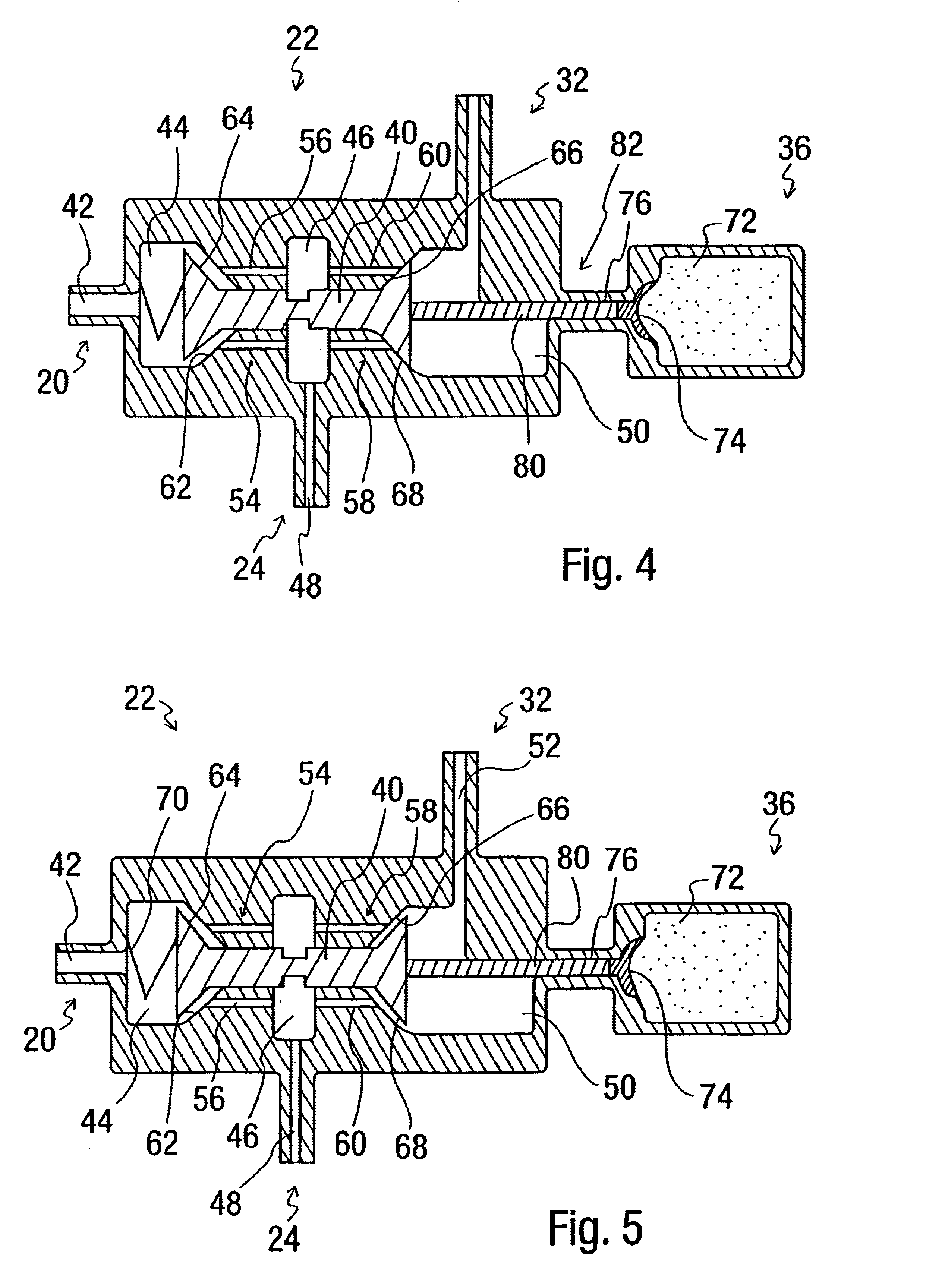
[0024]Referring to the drawings in particular, a heating system according to the present invention is designated in general by 10 in FIG. 1. A fuel line 14 leads from a fuel tank 12 to a metering pump 16, which may be of the conventional design. Another fuel line 18 leads from the metering pump 16 to a feed area 20 of a temperature-controlled fuel valve 22. The fuel introduced under increased pressure into the fuel valve 22 via the line 18 can be introduced via a first drain area 24 and another fuel line 26 into a combustion chamber 28 of a heating burner 30 in an area that is located close to a glow-type ignition pin or another igniting member 31. Furthermore, fuel can be introduced via a second drain area 32 and another line 34 from the fuel valve 22 into an area of the combustion chamber 28 that is located farther away from the glow-type ignition pin 31. It shall be pointed out here that the heating burner 30 may be an atomization burner or a vaporizing burner. The fuel is releas...


PUM


Abstract

A temperature-controlled fuel valve, especially for a fuel-operated heating burner of a vehicle heating system has at least one valve member (40) that is adjustable as a function of a temperature in the area of a heating burner (30).

Description

FIELD OF THE INVENTION[0001]The present invention pertains to a temperature-controlled fuel valve, which can be used especially in a fuel-operated heating burner of a vehicle heater.BACKGROUND OF THE INVENTION[0002]In heaters used in vehicles, which may be operated, e.g., as parking heaters or auxiliary heaters, the fuel is taken up, in general, in a metering pump from a fuel tank via a suction line and is introduced by the metering pump under pressure into the combustion chamber of the heating burner via a pressure pipe. To ignite the fuel introduced into the combustion chamber, e.g., by evaporation or atomization together with the combustion air, which is likewise introduced, at the beginning of a phase of operation, e.g., an igniting member designed as a glow-type ignition pin is provided.[0003]The problem arises during the operation of such systems that fuel is still present in the line section between the metering pump and the combustion chamber on switching off, and this fuel ...

Claims


Application Information

Patent Timeline
IPC IPC(8): B60H1/00B60H1/22F16K11/048F16K11/02F16K11/07F16K31/68F23N1/00F23N5/00
CPCB60H1/00485F16K11/048B60H1/2203B60H2001/2284
Inventor BAUER, THOMASBLASCHKE, WALTER
Owner J EBERSPAECHER GMBH & CO KG
Why Eureka
Try Eureka